Содержание
Hardware Abstraction
The library supports different protocols to access the OLED display. Currently there is support for I2C using the built in Wire.h library, I2C by using the much faster BRZO I2C library written in assembler and it also supports displays which come with the SPI interface.
I2C with Wire.h
#include <Wire.h>
#include "SSD1306Wire.h"

// for 128x64 displays:
SSD1306Wire display(0x3c, SDA, SCL);  // ADDRESS, SDA, SCL
// for 128x32 displays:
// SSD1306Wire display(0x3c, SDA, SCL, GEOMETRY_128_32);  // ADDRESS, SDA, SCL, GEOMETRY_128_32 (or 128_64)
// for using 2nd Hardware I2C (if available)
// SSD1306Wire(0x3c, SDA, SCL, GEOMETRY_128_64, I2C_TWO); //default value is I2C_ONE if not mentioned
// By default SD1306Wire set I2C frequency to 700000, you can use set either another frequency or skip setting the frequency by providing -1 value
// SSD1306Wire(0x3c, SDA, SCL, GEOMETRY_128_64, I2C_ONE, 400000); //set I2C frequency to 400kHz
// SSD1306Wire(0x3c, SDA, SCL, GEOMETRY_128_64, I2C_ONE, -1); //skip setting the I2C bus frequency
for a SH1106:
#include <Wire.h>
#include "SH1106Wire.h"

SH1106Wire display(0x3c, SDA, SCL);  // ADDRESS, SDA, SCL
// By default SH1106Wire set I2C frequency to 700000, you can use set either another frequency or skip setting the frequency by providing -1 value
// SH1106Wire(0x3c, SDA, SCL, GEOMETRY_128_64, I2C_ONE, 400000); //set I2C frequency to 400kHz
// SH1106Wire(0x3c, SDA, SCL, GEOMETRY_128_64, I2C_ONE, -1); //skip setting the I2C bus frequency
I2C with brzo_i2c
#include <brzo_i2c.h>
#include "SSD1306Brzo.h"

SSD1306Brzo display(0x3c, SDA, SCL);  // ADDRESS, SDA, SCL
or for the SH1106:
#include <brzo_i2c.h>
#include "SH1106Brzo.h"

SH1106Brzo display(0x3c, SDA, SCL);  // ADDRESS, SDA, SCL
SPI
#include <SPI.h>
#include "SSD1306Spi.h"

SSD1306Spi display(D0, D2, D8);  // RES, DC, CS
or for the SH1106:
#include <SPI.h>
#include "SH1106Spi.h"

SH1106Spi display(D0, D2);  // RES, DC
Подключение модуля OLED к Arduino Uno
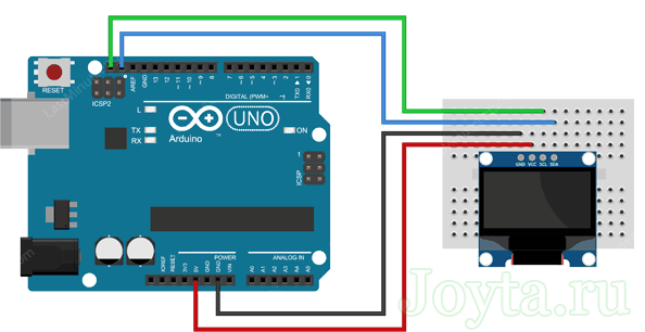
Прежде чем мы перейдем к загрузке кода и отправке данных на дисплей, давайте подключим дисплей к Arduino Uno.
Схема подключения довольно проста. Начните с подключения контакта VCC к выходу 5V на Arduino и GND к земле
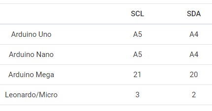
Теперь остались выводы, которые используются для связи по I2C. Обратите внимание, что каждая плата Arduino имеет разные контакты I2C
На платах Arduino с маркировкой R3 SDA (линия передачи данных) и SCL (линия синхронизации) находятся на разъемах рядом с выводом AREF. Они также известны как A5 (SCL) и A4 (SDA).
Если у вас MEGA, контакты будут другие! Используйте цифровые 21 (SCL) и 20 (SDA).
На следующей схеме показано как все должно быть подключено:
◆ CONTROLLER_NATIVE_SPI_BLOCK_8BIT_CMDS
| #define CONTROLLER_NATIVE_SPI_BLOCK_8BIT_CMDS | ( | column_cmd, | |
| row_cmd | |||
| ) |
Value:
static void set_block_native(lcduint_t x, lcduint_t y, lcduint_t w) \
{ \
uint8_t rx = w ? (x + w — 1) : (. — 1); \
ssd1306_intf.start(); \
ssd1306_spiDataMode(0); \
ssd1306_intf.send(column_cmd); \
ssd1306_intf.send(x); \
ssd1306_intf.send(rx < . ? rx : (. — 1)); \
ssd1306_intf.send(row_cmd); \
ssd1306_intf.send(y); \
ssd1306_intf.send(. — 1); \
ssd1306_spiDataMode(1); \
} \
static void next_page_native(void) \
{ \
} \
ssd1306_lcd_t ssd1306_lcd
Definition:
lcduint_t height
Definition:
lcduint_t width
Definition:
Macro generates 2 static functions, applicable for many oled controllers with 8-bit commands: set_block_native(), next_page_native(). These functions are to be used when working in oled controller native mode.
- Parameters
-
column_cmd command opcode for setting column address according to oled controller datasheet row_cmd command opcode for setting row address according to oled controller datasheet
- Note
- It is assumed that column and row commands accept 2 single byte arguments: start and end of region
Definition at line of file lcd_common.h.
Установка библиотеки для модуля OLED
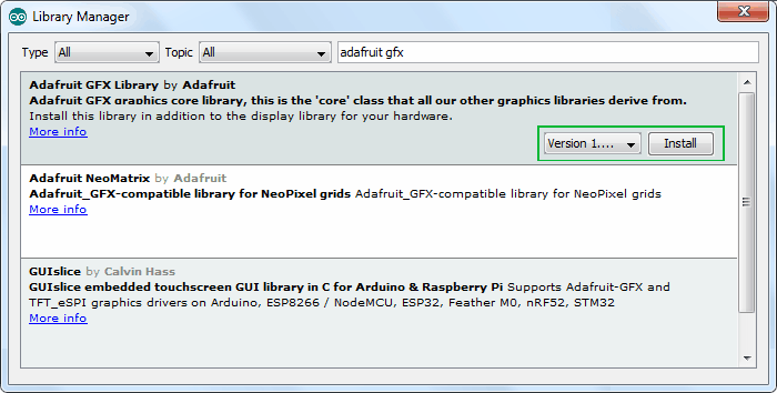
Контроллер SSD1306 OLED дисплея имеет гибкие, но сложные драйверы. Для использования контроллера SSD1306 необходимы огромные знания по адресации памяти. К счастью, была написана библиотека Adafruit SSD1306, которая позволяет довольно простыми и понятными командами управлять OLED дисплеем.
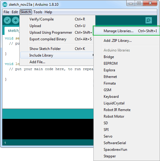
Чтобы установить библиотеку, перейдите в раздел Sketch > Include Library > Manage Libraries…. Подождите, пока менеджер библиотеки загрузит индекс библиотек и обновит список установленных библиотек.
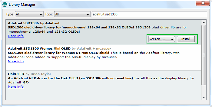
Отфильтруйте результаты поиска, введя adafruit ssd1306. Там должна быть пара записей. Ищите Adafruit SSD1306 от Adafruit. Нажмите на эту запись, а затем выберите Установить.
Библиотека Adafruit SSD1306 представляет собой аппаратную библиотеку, которая выполняет функции более низкого уровня. Она должна быть сопряжена с библиотекой Adafruit GFX для отображения графических примитивов, таких как точки, линии, круги, прямоугольники и т. д. Также установите и эту библиотеку.
Text operations
// Draws a string at the given location
void drawString(int x, int y, String text);

// Draws a String with a maximum width at the given location.
// If the given String is wider than the specified width
// The text will be wrapped to the next line at a space or dash
void drawStringMaxWidth(int x, int y, int maxLineWidth, String text);

// Returns the width of the String with the current
// font settings
int getStringWidth(String text);

// Specifies relative to which anchor point
// the text is rendered. Available constants:
// TEXT_ALIGN_LEFT, TEXT_ALIGN_CENTER, TEXT_ALIGN_RIGHT
void setTextAlignment(int textAlignment);

// Sets the current font. Available default fonts
// defined in SSD1306Fonts.h:
// ArialMT_Plain_10, ArialMT_Plain_16, ArialMT_Plain_24
// Or create one with the font tool at http://oleddisplay.squix.ch
void setFont(const char *fontData);
◆ ssd1306_printFixed()
| uint8_t ssd1306_printFixed | ( | uint8_t | xpos, |
| uint8_t | y, | ||
| const char * | ch, | ||
| style | |||
| ) |
Prints text to screen using fixed font.
- Parameters
-
xpos — horizontal position in pixels y — vertical position in pixels ch — NULL-terminated string to print style — font style (EFontStyle), normal by default.
- Returns
- number of chars in string
- See also
- Warning
- can output chars at fixed y positions: 0, 8, 16, 24, 32, etc. If you specify , will output text starting at position.
- Be careful with you flash space! Do not mix too many different functions in single sketch. uses much flash: ~396 bytes, needs 388 bytes. Placing both of these functions to your sketch will consume almost 1KiB.
Definition at line of file ssd1306_1bit.c.
Общие сведения об OLED дисплеях
OLED означает “Organic Light emitting diode“, что переводится как органический светоизлучающий диод, или, более коротко – органический светодиод. OLED дисплеи для радиолюбителей изготавливаются по той же самой технологии, что и большинство современных телевизоров, но имеют гораздо меньше пикселов по сравнению с ними. Но устройства на их основе (в том числе и с использованием Arduino) смотрятся потрясающе.
 |
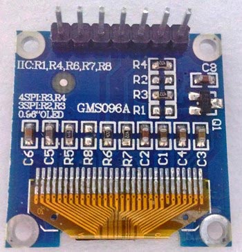 |
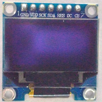
В нашем проекте мы будем использовать монохромный 7-пиновый SSD1306 0.96” OLED дисплей. Причина, по которой мы выбрали данный дисплей, заключается в том, что он может работать с тремя разными протоколами связи, трехпроводный SPI (Serial Peripheral Interface — последовательный интерфейс) режим, четырехпроводный SPI режим и режим IIC. В данной статье мы рассмотрим его подключение по четырехпроводному SPI режиму как самому скоростному из приведенных.
Контакты дисплея и выполняемые ими функции описаны в следующей таблице.
| Номер контакта | Название контакта | Альтернативное название контакта | Назначение контакта |
| 1 | Gnd | Ground | земля |
| 2 | Vdd | Vcc, 5V | напряжение питания (в диапазоне 3-5 В) |
| 3 | SCK | D0, SCL, CLK | контакт синхронизации (clock pin). Применяется в интерфейсах I2C и SPI |
| 4 | SDA | D1, MOSI | контакт данных. Применяется в интерфейсах I2C и SPI |
| 5 | RES | RST, RESET | контакт сброса модуля. Применяется в интерфейсе SPI |
| 6 | DC | A0 | контакт команд (Data Command pin). Применяется в интерфейсе SPI |
| 7 | CS | Chip Select (выбор чипа) | используется когда несколько устройств взаимодействуют по интерфейсу SPI |
Сообществом Arduino разработано достаточно много библиотек для работы с подобными дисплеями. Мы выбрали из них библиотеку Adafruit_SSD1306 как весьма простую и в то же время содержащую достаточно много полезных функций. Но если ваш проект имеет жесткие ограничения по памяти/скорости, то тогда вам лучше использовать библиотеку U8g поскольку она работает быстрее и занимает меньше места в памяти.
SPECIFICATIONS
Interface Pin Function
| No. | Symbol | Function |
|---|---|---|
| 1 | SDA | When serial interface mode is selected, D0 will be the serial clock input: SCLK; D1 will be the serial data input: SDIN. When I2C mode is selected, D2, D1 should be tied together and serve as SDAout, SDAin in application and D0 is the serial clock input, SCL. |
| 2 | SCL | |
| 3 | SA0 | In I2C mode, this pin acts as SA0 for slave address selection. When 3-wire serial interface is selected, this pin must be connected to VSS. |
| 4 | RST | This pin is reset signal input. When the pin is pulled LOW, initialization of the chip is executed. Keep this pin HIGH (i.e. connect to VDD) during normal operation. |
| 5 | CS | This pin is the chip select input. (active LOW). |
| 6 | VDD | 3.0V Power supply pin for core logic operation. |
| 7 | VIN | 5.0V Power supply pin for core logic operation. |
| 8 | GND | This is a ground pin. |
Mechanical Data
| Item | Dimension | Unit |
|---|---|---|
| Dot Matrix | 128 × 64 | Dots |
| Module dimension | 38.00 × 28.50 × 2.37 | mm |
| Active Area | 21.74 × 10.86 | mm |
| Pixel Size | 0.148 × 0.148 | mm |
| Pixel Pitch | 0.17 × 0.17 | mm |
| Display Mode | Passive Matrix | |
| Display Color | Monochrome | |
| Drive Duty | 1/64 Duty | |
| IC | SSD1306 | |
| Interface | I2C, SPI | |
| Size | 0.96 inch |
Absolute Maximum Ratings
| Parameter | Symbol | Min | Max | Unit |
|---|---|---|---|---|
| Supply Voltage for Logic | VDD | 1.65 | 3.3 | V |
| Supply Voltage for Logic | VIN | 4.0 | 6.0 | V |
| Operating Temperature | TOP | -40 | +80 | °C |
| Storage Temperature | TSTG | -40 | +85 | °C |
Electronical Characteristics
| Item | Symbol | Condition | Min | Typ | Max | Unit |
|---|---|---|---|---|---|---|
| Supply Voltage for Logic(3V) | VDD | - | 2.8 | 3.0 | 3.2 | V |
| Supply Voltage for Logic(5V) | VIN | - | 4.8 | 5.0 | 5.2 | V |
| Input High Volt. | VIH | - | 0.8×VDD | - | VDDIO | V |
| Input Low Volt. | VIL | - | - | 0.2×VDD | V | |
| Output High Volt. | VOH | - | 0.9×VDD | - | VDDIO | V |
| Output Low Volt. | VOL | - | - | 0.1×VDD | V | |
| 50% Check Board operating Current | ICC | Vcc=7.5V | - | 12.0 | 22.0 | mA |
Search keyword: 128×64 oled, oled 128×64, 0.96″ oled, 0.96 inch oled, oled 0.96″,12864 oled, oled 12864,oled 128×64 spi,oled 128×64 ssd1306
Key Features
- Supports color, monochrome OLED displays, and VGA monitor
- The library has modular structure, and some modules can be excluded from compilation at all to reduce flash usage.
- Needs very little RAM (Attiny85 with Damellis package needs minimum 25 bytes of RAM to communicate with OLED)
- Fast implementation to provide reasonable speed on slow microcontrollers
- Supports i2c and spi interfaces:
- i2c (software implementation, Wire library, AVR Twi, Linux i2c-dev)
- spi (4-wire spi via Arduino SPI library, AVR Spi, AVR USI module)
- Primitive graphics functions (lines, rectangles, pixels, bitmaps)
- Printing text to display (using fonts of different size, you can use GLCD Font Creator to create new fonts)
- Includes graphics engine to support double buffering on tiny microcontrollers.
- Can be used for game development (bonus examples):
- Arkanoid game (arkanoid in old style API and arkanoid8 in new style API)
- Simple Lode runner game.
- Snowflakes
The i2c pins can be changed via API functions. Please, refer to documentation. Keep in mind, that the pins, which are allowed for i2c or spi interface, depend on the hardware. The default spi SCLK and MOSI pins are defined by SPI library, and DC, RST, CES pins are configurable through API.
Introduction
SSD1306 driver is Arduino style C/C++ library with unicode support. The library can be compiled for plain Linux
(for example, raspberry spi), or you can use it with plain avr-gcc compiler without Arduino IDE. It supports
monochrome and RGB oleds and has debug mode, allowing to execute code on PC, using SDL2.0.
Initially the library is intended for very small microcontrollers (with a little of RAM). It was developed to use as
few resources as possible, but still has powerful capabilities (NanoEngine), allowing to develop nice animation.
It works on any powerful devices like raspberry pi, esp32; and can be easily ported to new platform.
Настройка управления и частот
Установка пропорции делителя частоты
Код команды: , где:
- — младшие четыре бита, которые определяют пропорцию делителя частоты (Display CLock) относительно .. Делитель устанавливается в . При сбросе SSD1306 , поэтому в делителе будет единица. Обратитесь к разделу 8.3 даташита.
- — старшие четыре бита, которые определяют частоту . Разрешённый диапазон . При сброме SSD1306 в заносится . При увеличении этого значения, увеличивается частота и наоборот.
Установка периода предварительной зарядки
Код команды: , где:
- — младшие четыре бита, которые определяют период фазы 1 (см. даташит) до 15 , значение запрещено. При сбросе SSD1306 .
- — старшие четыре бита, которые определяют период фазы 2 (см. даташит) до 15 , значение запрещено. При сбросе SSD1306 .
Команда используется для установки длительности периода предварительной зарядки. Интервал считается в , где равен двум .
Код команды: , где:
- — ~0.65 x VCC;
- — ~0.77 x VCC (после сброса SSD1306);
- — ~0.83 x VCC.
DESCRIPTION
Winstar OLED 12864, SSD1306 OLED Display
Winstar released two new COG structure OLED 12864 with PCB board models, WEA012864D-01 version and WEA012864D-03 version; these two OLED display module are made of 128×64 pixels, diagonal size 0.96 inch. WEA012864D-01 module is built in with SSD1306 IC, it supports I2C (default), SPI interface optional, VCC 3V /5V, I/O level 5V to 3V, with conversion circuit, 1/64 duty cycle. The WEA012864D-01 model is having PCB outline size 38.0×28.5×2.37 mm with mounting holes on board and 8 metal pins on module.
This 128×64 SSD1306 OLED display module is suitable for smart control, industrial control for heater, smart home application, medical device, etc. This module can be operating at temperatures from -40℃ to +80℃; its storage temperatures range from -40℃ to +85℃.
◆ ssd1306_printFixedN()
| uint8_t ssd1306_printFixedN | ( | uint8_t | xpos, |
| uint8_t | y, | ||
| const char | ch[], | ||
| style, | |||
| uint8_t | factor | ||
| ) |
Prints text to screen using size fixed font, scaled by factor value.
Factor value 0 gives regular font size (6×8 for example)
Factor value 1 gives double font size (12×16 if 6×8 font is used)
Factor value 2 gives fourth font size (24×32 if 6×8 font is used)
Factor value 3 gives eighth font size (48×64 if 6×8 font is used)
- Parameters
-
xpos — horizontal position in pixels y — vertical position in pixels ch — NULL-terminated string to print style — font style (EFontStyle), normal by default. factor — 0, 1, 2, 3.
- Returns
- number of chars in string
- See also
- Warning
- can output chars at fixed y positions: 0, 8, 16, 24, 32, etc. If you specify , will output text starting at position.
- Be careful with you flash space! Do not mix too many different functions in single sketch. uses much flash: ~474 bytes, needs 388 bytes. Placing both of these functions to your sketch will consume almost 1KiB.
Definition at line of file ssd1306_1bit.c.
Introduction
SSD1306 driver is Arduino style C/C++ library with unicode support. The library can be compiled for plain Linux (for example, raspberry spi), or you can use it with plain avr-gcc compiler without Arduino IDE, or with ESP32 IDF. It supports monochrome and RGB oleds and has debug mode, allowing to execute code on PC, using SDL2.0. Initially the library is intended for very small microcontrollers (with a little of RAM). It was developed to use as few resources as possible, but still has powerful capabilities, allowing to develop nice animation. It works on any powerful devices like raspberry pi, esp32; and can be easily ported to new platform.
Since ssd1306 library supports different display types: monochrome, 8-bit color, 16-bit color displays, — there are several group of API functions:
- Generic API functions (font specific, cursor positioning, menu implementation)
- 1-bit API functions for monochrome displays (these ones can be used both for color and mono lcd)
- 8-bit API functions for color displays (these ones work only for color displays)
- 16-bit API functions for color displays (only color displays)
Also, for graphics animation there special C++ API, called Nano Engine.
Ui Library (OLEDDisplayUi)
The Ui Library is used to provide a basic set of user interface elements called and . A is used to provide
information to the user. The default behaviour is to display a for a defined time and than move to the next . The library also
provides an element that will be updated accordingly. An on the other hand is a piece of information (e.g. a clock) that
is always displayed at the same position.
/**
 * Initialise the display
 */
void init();

/**
 * Configure the internal used target FPS
 */
void setTargetFPS(uint8_t fps);

/**
 * Enable automatic transition to next frame after the some time can be configured with
 * `setTimePerFrame` and `setTimePerTransition`.
 */
void enableAutoTransition();

/**
 * Disable automatic transition to next frame.
 */
void disableAutoTransition();

/**
 * Set the direction if the automatic transitioning
 */
void setAutoTransitionForwards();
void setAutoTransitionBackwards();

/**
 *  Set the approx. time a frame is displayed
 */
void setTimePerFrame(uint16_t time);

/**
 * Set the approx. time a transition will take
 */
void setTimePerTransition(uint16_t time);

/**
 * Draw the indicator.
 * This is the default state for all frames if
 * the indicator was hidden on the previous frame
 * it will be slided in.
 */
void enableIndicator();

/**
 * Don't draw the indicator.
 * This will slide out the indicator
 * when transitioning to the next frame.
 */
void disableIndicator();

/**
 * Enable drawing of all indicators.
 */
void enableAllIndicators();

/**
 * Disable drawing of all indicators.
 */
void disableAllIndicators();

/**
 * Set the position of the indicator bar.
 */
void setIndicatorPosition(IndicatorPosition pos);

/**
 * Set the direction of the indicator bar. Defining the order of frames ASCENDING / DESCENDING
 */
void setIndicatorDirection(IndicatorDirection dir);

/**
 * Set the symbol to indicate an active frame in the indicator bar.
 */
void setActiveSymbol(const uint8_t* symbol);

/**
 * Set the symbol to indicate an inactive frame in the indicator bar.
 */
void setInactiveSymbol(const uint8_t* symbol);

/**
 * Configure what animation is used to transition from one frame to another
 */
void setFrameAnimation(AnimationDirection dir);

/**
 * Add frame drawing functions
 */
void setFrames(FrameCallback* frameFunctions, uint8_t frameCount);

/**
 * Add overlays drawing functions that are draw independent of the Frames
 */
void setOverlays(OverlayCallback* overlayFunctions, uint8_t overlayCount);

/**
 * Set the function that will draw each step
 * in the loading animation
 */
void setLoadingDrawFunction(LoadingDrawFunction loadingDrawFunction);

/**
 * Run the loading process
 */
void runLoadingProcess(LoadingStage* stages, uint8_t stagesCount);

// Manual control
void nextFrame();
void previousFrame();

/**
 * Switch without transition to frame `frame`.
 */
void switchToFrame(uint8_t frame);

/**
 * Transition to frame `frame`. When the `frame` number is bigger than the current
 * frame the forward animation will be used, otherwise the backwards animation is used.
 */
void transitionToFrame(uint8_t frame);

// State Info
OLEDDisplayUiState* getUiState();

// This needs to be called in the main loop
// the returned value is the remaining time (in ms)
// you have to draw after drawing to keep the frame budget.
int8_t update();
Arduino I2C OLED display подключение
OLED (Organic Light-Emitting Diode) — это полупроводниковый прибор, излучающий свет при прохождении через него электрического тока. Управление модулем осуществляет с помощью чипа SSD1306, который поддерживает пять разных протоколов связи. Встречаются модули не только с протоколом IIC, но и с протоколом SPI, и даже олед дисплеи с возможностью выбора (переключения) между этими двумя протоколами.
Характеристики OLED I2C 128×64 / 128×32
- Цвет экрана — монохромный;
- Разрешение — 128×64 или 128×32;
- Графический чип — SSD1306;
- Интерфейс — I2C или SPI;
- Питание модуля — от 3 до 5 В;
- Размер модуля — 27x27x4 мм.
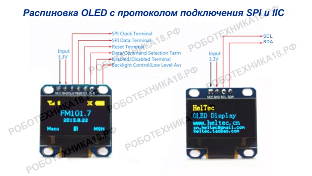
Распиновка OLED SPI и дисплея OLED IIC
Главным плюсом OLED 128×64 iic является работа модуля без подсветки, за счет чего обеспечивается низкое потребление тока этим модулем. А высокое разрешение OLED 128×64 px Arduino позволяет вывести на дисплей большее количество информации, в отличии от текстового экрана 1602. Для подключения используется четыре разъема — два провода для питания (5V и GND) и два провода для шины IIC (SDA и SCL).
API
Display Control
// Create the display object connected to pin sda and sdc
SSD1306(int i2cAddress, int sda, int sdc);

// Initialize the display
void init();

// Cycle through the initialization
void resetDisplay(void);

// Connect again to the display through I2C
void reconnect(void);

// Turn the display on
void displayOn(void);

// Turn the display offs
void displayOff(void);

// Clear the local pixel buffer
void clear(void);

// Write the buffer to the display memory
void display(void);

// Set display contrast
void setContrast(char contrast);

// Turn the display upside down
void flipScreenVertically();

// Send a command to the display (low level function)
void sendCommand(unsigned char com);

// Send all the init commands
void sendInitCommands(void);
Render the scene #
The node is your main tool to display . The processes a single branch of the graphic tree created using the graphics library, renders it, and displays at the device.
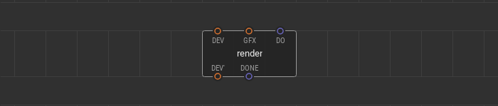
A graphic tree branch to render links to the input pin. A pulse signal at the pin is a trigger to process the graphic scene and display it. If the scene is rendered, a pulse comes to the output pin.
Use multiple nodes simultaneously. Processing various branches of the graphic tree at a different time, you can show dynamic graphic scenes at the screen.
Here is the example of a three nodes use. The tree of graphic elements consists of a and two on it. The device node and three nodes are linked together in a daisy chain. All nodes have different triggering algorithms at their pins.
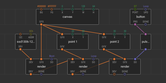
The first is on ; it fills the display screen with a specified only once — after powering the device. The second is responsible for on the canvas. Its trigger is set to . It means that any changes in the position are immediately shown on the screen. The third is responsible for displaying the and its trigger is linked to the . Here you can also change the position, but the changes are displayed only after the button click.
OLED I2C Display Tutorial with Arduino
We’ve provided our OLED I2C Display modules for your selection but now its time to learn how to actually use them with an Arduino! For today’s simple tutorial to help you get started, we’ll be using the Grove – OLED Display 0.96″ (SSD1315)!
Note: The Grove – OLED Display 0.96″ is also supported on other platforms like the Raspberry Pi, Beaglebone, and LinkIt ONE. For each of their tutorials, please refer to our Wiki page here!
Required Materials
To follow along with today’s tutorial, you’ll need the following items!
- Seeeduino V4.2
- Grove Base Shield V2.0 for Arduino
- Grove OLED Display 0.96″ (SSD1315)
Seeeduino is Seeed’s very own Arduino board, designed with relative benefits over the original. If you do not wish to purchase a Seeeduino, this tutorial is still applicable for the following Arduino boards: Arduino UNO, Arduino Mega, Arduino Leonardo, Arduino 101, Arduino Due
You can also use any Grove-compatible Arduino system that has I2C interface capabilities, such as the Wio Terminal, or the Seeeduino XIAO with its Grove Shield or Expansion Board.
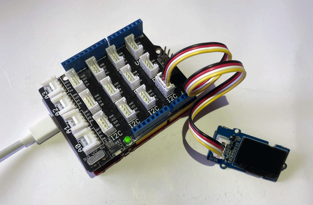
Hardware Assembly
Step 1: Plug Grove-Base Shield into Seeeduino
Step 2: Plug the Grove OLED Display 0.96″ into any I2C port on your device.
Step 3: Connect your device to PC via a USB cable.
If you are using the Seeeduino V4.2 with its Grove Base Shield, you should have something like this:
Software Configuration with Arduino Code and Library
Step 1. Navigate to Sketch -> Include Library -> Manage Libraries… . Search for and Install library in the Library Manager.
Step 2: Open the Arduino IDE and create a new file, then copy the following code into the new file.
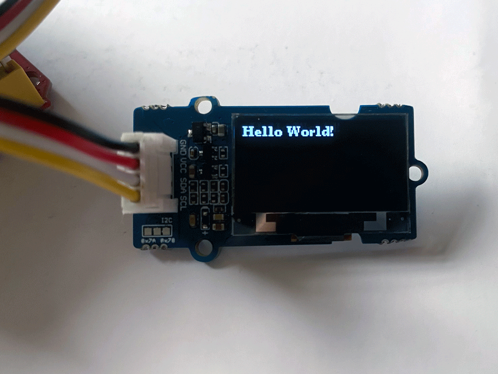
Step 3: Upload the code to your Arduino device. If you’re unsure on how to upload the code, kindly check here.
And that’s all for this tutorial! You should now see “Hello World” on the screen, like below.
Going Further with Graphics Libraries
OLED Displays aren’t just useful for displaying text – you can also display shapes and even produce animations by refreshing the screen quickly! To do these, we will usually employ the help of graphics libraries, like U8g2.
U8g2 is a monochrome graphics library for embedded devices. U8g2 supports monochrome OLEDs and LCDs, which includes the SSD1315. The U8g2 also conveniently includes U8x8 library:
U8g2
- Includes all graphics procedures (line/box/circle draw).
- Supports many fonts. (Almost) no restriction on the font height.
- Requires some memory in the microcontroller to render the display.
U8x8
- Text output only (character) device.
- Only fonts allowed with fit into a 8×8 pixel grid.
- Writes directly to the display. No buffer in the microcontroller required.
For more details, kindly visit the U8g2 Library Wiki as well as the U8g2 API Reference page.
Pixel drawing
/* Drawing functions */
// Sets the color of all pixel operations
// color : BLACK, WHITE, INVERSE
void setColor(OLEDDISPLAY_COLOR color);

// Draw a pixel at given position
void setPixel(int16_t x, int16_t y);

// Draw a line from position 0 to position 1
void drawLine(int16_t x0, int16_t y0, int16_t x1, int16_t y1);

// Draw the border of a rectangle at the given location
void drawRect(int16_t x, int16_t y, int16_t width, int16_t height);

// Fill the rectangle
void fillRect(int16_t x, int16_t y, int16_t width, int16_t height);

// Draw the border of a circle
void drawCircle(int16_t x, int16_t y, int16_t radius);

// Fill circle
void fillCircle(int16_t x, int16_t y, int16_t radius);

// Draw an empty triangle i.e. only the outline
void drawTriangle(int16_t x0, int16_t y0, int16_t x1, int16_t y1, int16_t x2, int16_t y2);

// Draw a solid triangle i.e. filled
void fillTriangle(int16_t x0, int16_t y0, int16_t x1, int16_t y1, int16_t x2, int16_t y2);

// Draw a line horizontally
void drawHorizontalLine(int16_t x, int16_t y, int16_t length);

// Draw a lin vertically
void drawVerticalLine(int16_t x, int16_t y, int16_t length);

// Draws a rounded progress bar with the outer dimensions given by width and height. Progress is
// a unsigned byte value between 0 and 100
void drawProgressBar(uint16_t x, uint16_t y, uint16_t width, uint16_t height, uint8_t progress);

// Draw a bitmap in the internal image format
void drawFastImage(int16_t x, int16_t y, int16_t width, int16_t height, const uint8_t *image);

// Draw a XBM
void drawXbm(int16_t x, int16_t y, int16_t width, int16_t height, const uint8_t *xbm);
◆ ssd1331_copyBlock()
| void ssd1331_copyBlock | ( | uint8_t | left, |
| uint8_t | top, | ||
| uint8_t | right, | ||
| uint8_t | bottom, | ||
| uint8_t | newLeft, | ||
| uint8_t | newTop | ||
| ) |
Copies block in GDRAM to new position
- Parameters
-
left column start of block to copy top row start of block to copy right column end of block to copy bottom row end of block to copy newLeft new column start newTop new row start
- Note
- This API can be used only with ssd1331 RGB oled displays
- after copy command is sent, it takes some time from oled controller to complete operation. So, it is HIGHLY recommended to wait for reasonable time before send other graphics operations (for example, use 250us delay). This time is required for oled display to become ready to accept new commands.
Definition at line of file oled_ssd1331.c.
Features
- Draw pixels at given coordinates
- Draw lines from given coordinates to given coordinates
- Draw or fill a rectangle with given dimensions
- Draw Text at given coordinates:
- Define Alignment: Left, Right and Center
- Set the Fontface you want to use (see section Fonts below)
- Limit the width of the text by an amount of pixels. Before this widths will be reached, the renderer will wrap the text to a new line if possible
- Display content in automatically side scrolling carousel
- Define transition cycles
- Define how long one frame will be displayed
- Draw the different frames in callback methods
- One indicator per frame will be automatically displayed. The active frame will be displayed from inactive once
Похожие записи:
 Какие породы деревьев лучше всего подходят для растопки бани
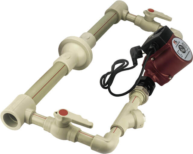 Установка насоса в систему отопления частного дома
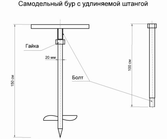 Все об электробурах
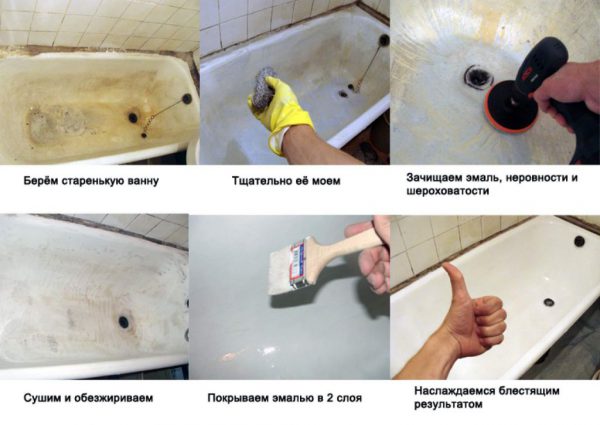 Ремонт ванны акрилом: восстановление эмали в подробностях
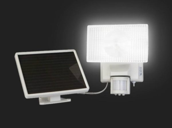 Как сделать садовый светильник от солнечной батареи своими руками
 Размер осб листа стандартный: характеристики и свойства