Содержание
Battery Backup
The DS3231 incorporates a battery input, and maintains accurate timekeeping when main power to the device is interrupted.
The built-in power-sense circuit continuously monitors the status of VCC to detect power failures and automatically switches to the backup supply. So, you need not worry about power outages, your MCU can still keep track of time.
The bottom side of the board holds a battery holder for 20mm 3V lithium coincells. Any CR2032 battery can fit well.
Assuming a fully charged CR2032 battery with capacity 220mAh is used and chip consumes its minimum 3µA, the battey can keep the RTC running for a minimum of 8 years without an external 5V power supply.
220mAh/3µA = 73333.34 hours = 3055.56 days = 8.37 years
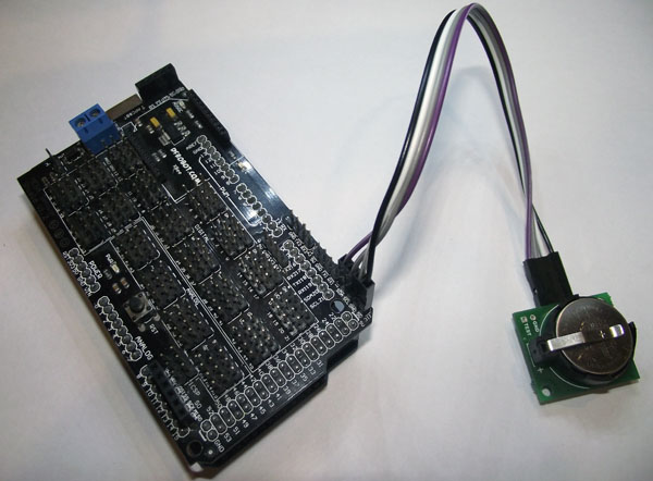
Подключение модуля MP1095 к Arduino
Для подключения к Arduino Mega 2560 различных устройств и датчиков я использую шилд под названием MEGA Sensor. И для использования шины I2C на нем выведены отдельные пины. Очень удобно, надо сказать.
На плате Arduino Mega дополнительные пины шины I2C соответствуют аналоговым выводам 20 и 21 (тоже самое справедливо и для Arduino Due). Для Arduino Uno это выводы 4 и 5, 2 и 3 в случае Arduino Leonardo. Ориентироваться нужно на названия пинов SDA и SCL.
- VDD используется для питания микросхемы RTC для получения с него временных данных. Если напряжение +5 В отсутствует, микросхема переходит в спящий режим для сохранения и отсчета времени.
- GND — земля (общий провод)
- SCL — тактирующий вывод I2C интерфейса (нужен для коммуникации с часами реального времени)
- SDA — вывод данных I2C интерфейса (нужен для коммуникации с RTC)
- SQW (на некоторых аналогичных модулях RTC) — дополнительный выход прямоугольного сигнала частотой 32768 Гц. В большинстве случаев не используется.
Подключите аналоговый 20 пин Arduino Mega (аналоговый 4 пин для других плат Arduino) к выводу SDA модуля и 21 пин (5 — для других плат) к выводу SCL.
Проблемы
Да, этот код рабочий, и часы будут идти. Однако, если отключить питание, а через несколько минут включить, то после включения время время вновь станет тем, которое было при компиляции.
Это происходит потому что после включения питания, вновь исполняется код, находящийся в функции . А он записывает в часы реального времени старое значение времени.
Чтобы этого избежать, нам необходимо еще чуть-чуть модифицировать код. Каждый раз в функции будет происходить подсчет «хэша» времени компиляции — будет рассчитываться количество секунд, прошедшее с 00:00:00 до времени компиляции. И этот хэш будет сравниваться с хэшем в EEPROM. Напомним EEPROM — память, которая не обнуляется при отключении питания.
Если значения посчитанного и сохранённого ранее хэша совпадают, то это значит, что перезаписывать время в модуль часов нет необходимости: это уже было сделано. А вот если эта проверка не проходит, то происходит перезапись времени в RTC.
Для записи/чтения числа типа в/из EEPROM написаны две дополнительные функции и . Они добавлены потому что функции и могуть читать и писать только данные типа .
- rtc-eeprom.ino
-
#include <Wire.h>
#include <EEPROM.h>
#include "TM1637.h"
#include "DS1307.h"

//Массив, содержащий время компиляции
char compileTime = __TIME__;

//Номера пинов Arduino, к которым подключается индикатор
#define DISPLAY_CLK_PIN 12
#define DISPLAY_DIO_PIN 13

//Для работы с микросхемой часов и индикатором мы используем библиотеки
TM1637 display(DISPLAY_CLK_PIN, DISPLAY_DIO_PIN);
DS1307 clock;


void setup()
{

  //Включаем и настраиваем индикатор
  display.set();
  display.init();

  //Запускаем часы реального времени
  clock.begin();

  //Получаем число из строки, зная номер первого символа
  byte hour = getInt(compileTime, );
  byte minute = getInt(compileTime, 3);
  byte second = getInt(compileTime, 6);

  //Импровизированный хэш времени
  //Содержит в себе количество секунд с начала дня
  unsigned int hash =  hour * 60 * 60 + minute  * 60 + second;

  //Проверяем несовпадение нового хэша с хэшем в EEPROM
  if (EEPROMReadInt() != hash) {

    //Сохраняем новый хэш
    EEPROMWriteInt(, hash);

    //Готовим для записи в RTC часы, минуты, секунды
    clock.fillByHMS(hour, minute, second);

    //Записываем эти данные во внутреннюю память часов.
    //С этого момента они начинают считать нужное для нас время
    clock.setTime();
  }

}


void loop()
{
  //Значения для отображения на каждом из 4 разрядов
  int8_t timeDisp4;

  //Запрашиваем время с часов
  clock.getTime();

  //Получаем десятки часов с помощью целочисленного деления
  timeDisp = clock.hour  10;

  //Получаем единицы часов с помощью остатка от деления
  timeDisp1 = clock.hour % 10;

  //Проделываем то же самое с минутами
  timeDisp2 = clock.minute  10;
  timeDisp3 = clock.minute % 10;

  //... а затем выводим его на экран
  display.display(timeDisp);

  //у нас нет отдельных разрядов для секунд, поэтому
  //будем включать и выключать двоеточие каждую секунду
  display.point(clock.second % 2 ? POINT_ON  POINT_OFF);

}

char getInt(const char* string, int startIndex) {
  return int(stringstartIndex - '0') * 10 + int(stringstartIndex+1) - '0';
}

//Запись двухбайтового числа в память
void EEPROMWriteInt(int address, int value)
{
  EEPROM.write(address, lowByte(value));
  EEPROM.write(address + 1, highByte(value));
}

//Чтение числа из памяти
unsigned int EEPROMReadInt(int address)
{
  byte lowByte = EEPROM.read(address);
  byte highByte = EEPROM.read(address + 1);

  return (highByte << 8) | lowByte;
}
Использование DS3231 для пробуждения Ардуино
Итак, наша задача — перевести Ардуино в режим энергосбережения и периодически просыпаться по будильнику для выполнения каких-то действий. Попробуем, например, мигать встроенным светодиодом при пробуждении Ардуино. Практически всё, что нам для этого нужно, уже есть в приведённом выше скетче. Остаётся лишь добавить переход в режим энергосбережения:
#include <avr/sleep.h>
#include <Wire.h>
#include <DS3231.h>

DS3231 clock;

void alarmFunction() {

}

void setup() {

  clock.begin();
  clock.enableOutput(false);
  clock.armAlarm1(false);
  clock.armAlarm2(false);
  clock.clearAlarm1();
  clock.clearAlarm2();


  clock.setAlarm1(, , , 10, DS3231_MATCH_S);


  pinMode(2, INPUT_PULLUP);
  attachInterrupt(, alarmFunction, FALLING);

  pinMode(13, OUTPUT);
  ADCSRA &= ~(1 << ADEN);
}

void loop() {

  set_sleep_mode(SLEEP_MODE_PWR_DOWN);
  noInterrupts();
  sleep_enable();
  MCUCR = bit (BODS) | bit (BODSE);
  MCUCR = bit (BODS);
  interrupts();
  sleep_cpu();


  sleep_disable();


  if (clock.isAlarm1()) {

    clock.clearAlarm1();

    digitalWrite(13, HIGH);
    delay(2000);
    digitalWrite(13, LOW);

  }
}
В данном примере будильник 1 устанавливается на срабатывание в 10 секунд каждой минуты, после чего Ардуино переводится в режим энергосбережения. Доступные для Ардуино (ATmega328P) режимы энергосбережения, а также события, пробуждающие микроконтроллер, я приводил в статье Режимы энергосбережения Ардуино. Проснувшись, не лишним будет проверить флаг будильника, чтобы убедиться, что именно он нас разбудил. Если флаг будильника 1 установлен, то можем выполнять наш код, в данном случае — включение и выключение светодиода.
Будильник не обязательно должен настраиваться единожды, как в приведённых выше скетчах. Его можно менять хоть при каждом срабатывании. Так можно добиться пробуждения Ардуино через определённый интервал времени. Например, чтобы будильник срабатывал каждые 10 минут, его нужно выставлять при каждом пробуждении на текущее время + 10 минут. Это потребует минимальных изменений приведённого выше скетча:
    ...

    clock.clearAlarm1();
    RTCDateTime dt = clock.getDateTime();
    clock.setAlarm1(, , (dt.minute + 10) % 60, dt.second, DS3231_MATCH_M_S);
    ...
How to interface DS3231 RTC Module with a microcontroller?
The interfacing is straightforward. Just power-up(not more than 5 Volts to avoid damage) the RTC either through a power supply or through the controller and then wire the SCL to the SCL and SDA to the SDA of the module and the microcontroller, respectively. The transmission takes place through synchronous inter-integrated circuit (I2C) protocol, which is quite complex.
The libraries written for the RTC module can help to ease up things. If they are included in the program, they will automatically provide the date and time to the user. Furthermore, these libraries can help us to change or set the alarm clock.
The module comes with a battery in case there is a power-out situation. It will help the module to stay updated with the date and time.
Interfacing DS3231 RTC with Arduino
As explained earlier, we will interface an Arduino UNO with RTC as an example:
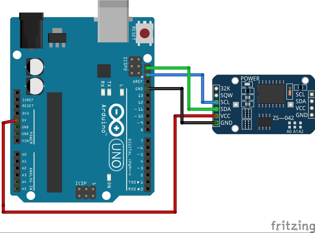
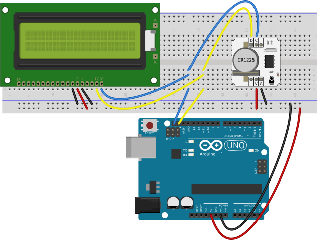
Connect the pins accordingly.
| Arduino UNO | RTC Module |
|---|---|
| 5V | VCC |
| GND | GND |
| ICSP2 Header | SDA |
| ICSP2 Header | SCL |
Install DS3231 RTC Library in Arduino IDE
To program a DS3231 RTC module, we need to use I2C communication pins of Arduino. If you don’t know about I2C communication, you can check these articles:
But it requires an effort to write a code from scratch. Fortunately, an Arduino RTClib library is available which provides callback functions to take time measurements from an RTC module. This library hides all the complexity to communicate with an RTC module over I2C communication. We can use simple callback functions implemented by RTClib to read data from DS3231.
Therefore, to program a DS3231 RTC module with Arduino, you will use the RTClib library available in Arduino IDE.
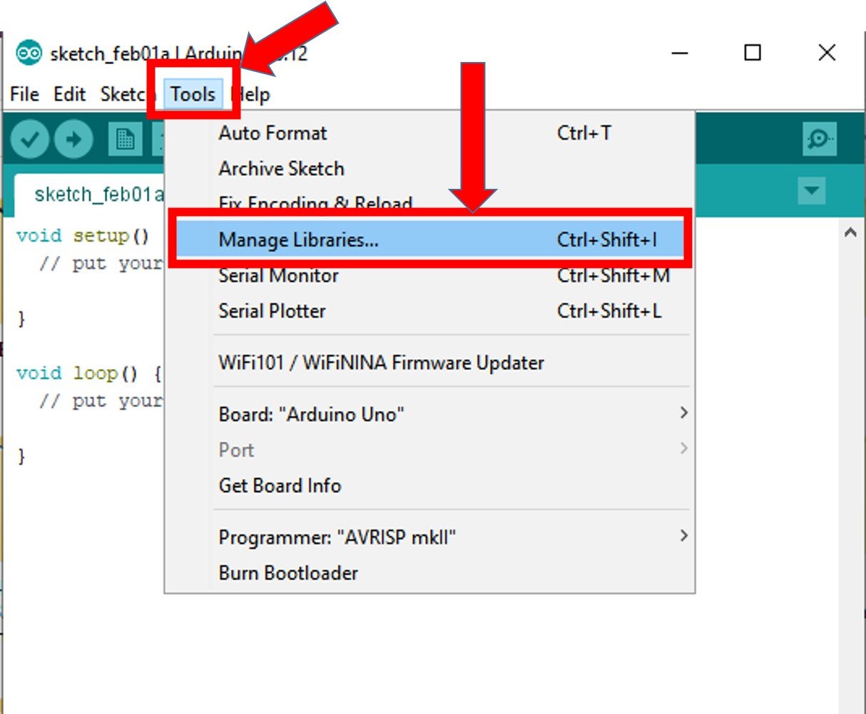
To use this library, first, we need to install this library in Arduino IDE by going to Arduino’s library manager. Open Arduino IDE, go to Tools > Manage Libraries.
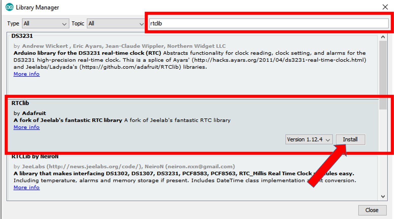
After that, this window library manager window will appear. Search for “RTClib” by typing in the search bar. You will see many options for DS3231. But the one that we will use in this tutorial is RTClib by Adafruit. Select RTClib by Adafruit and click on the install button.
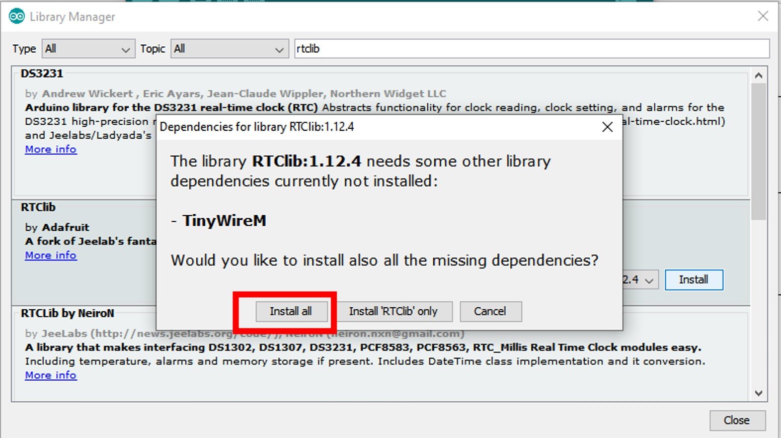
When you click on the install button, you may get a message that RTClib may require other libraries dependencies which is currently not installed in your Arduino IDE. We recommend you to install all dependencies by clicking on install button. Otherwise, RTClib will not work properly.
Arduino Code
This example code performs time settings. Also, this Arduino sketch read time and data from DS3231 RTC module and prints in on Arduino serial monitor.
The results can be observed through the Serial Monitor. It will display the updated time and date.
- DS1302
- DS1307
Compact Alarm with Card Reader and RTC
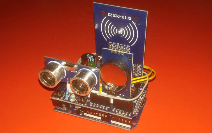
With this alarm, you can tell whenever someone enters your house which can be turned on and off with a card reader and also automatically activated with the RTC!
What do you need?
- Arduino Uno Rev3 / Seeeduino V4.2 ($6.90)
- Bread board Clear – 8.2 x 5.3cm
- LED (Generic)
- Resistor 221 ohm
- Grove – Ultrasonic Distance Sensor
- Grove – Buzzer
- Grove – RTC
- RC522 Card Reader
Interested? You can check out the full tutorial by Simonee Adobs on Arduino Project Hub here!
OLED RTC Clock
With an RTC module, you can of course also make your OLED digital clock with the Arduino which shows the date, time and day!
What do you need
- Arduino Uno Rev3 / Seeeduino V4.2 ($6.90) or Arduino Nano v3 / Seeeduino Nano
- Grove – RTC
- Grove – OLED Display 1.12” V2
- 2 x Grove – Button
- 32.768KHz crystal oscillator
- 2 x 10K ohm resistor
- 3V coin cell battery
Interested? You can find the full tutorial on Simple Projects!
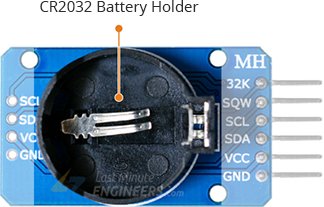
DS3231 RTC Module Pinout
The following figure shows the pinout diagram of the DS3231 RTC Module:

Pin Configuration
Let us discuss the pinout of the DS3231 Real-time Module. The pin configuration detail in tabular is mentioned below:
| Pin Name | Function |
|---|---|
| VCC | Power Supply pin |
| GND | Ground pin |
| SQW | Square-wave Output pin |
| SCL | Serial Clock pin |
| SDA | Serial Data pin |
| 32K | 32KHz Open-drain Output pin |
- SQW: It is used to generate square wave or to be used as an interrupt for the alarms
- SCL: A serial clock line used to synchronize data transmissions. It is a part of the I2C interface.
- SDA: A serial data transmission line. It is a part of the I2C interface.
- 32K: This pin is used for a reference clock.
Общие сведения
Использовании модуля DS1307 зачастую очень оправдано, например, когда данные считываются редко, интервалом более недели, использовать собственные ресурсы контроллера, неоправданно или невозможно. Обеспечивание бесперебойное питание, например платы Arduino, на длительный срок дорого, даже при использовании батареи.
Благодаря собственной памяти и автономностью, можно регистрировать события, (при автономном питании) например изменение температуры и так далее, данные сохраняются в памяти их можно считать из памяти модуля. Так что модуль DS1307 часто используют, когда контроллерам Arduino необходимо знать точное время, для запуска какого то события и так далее.
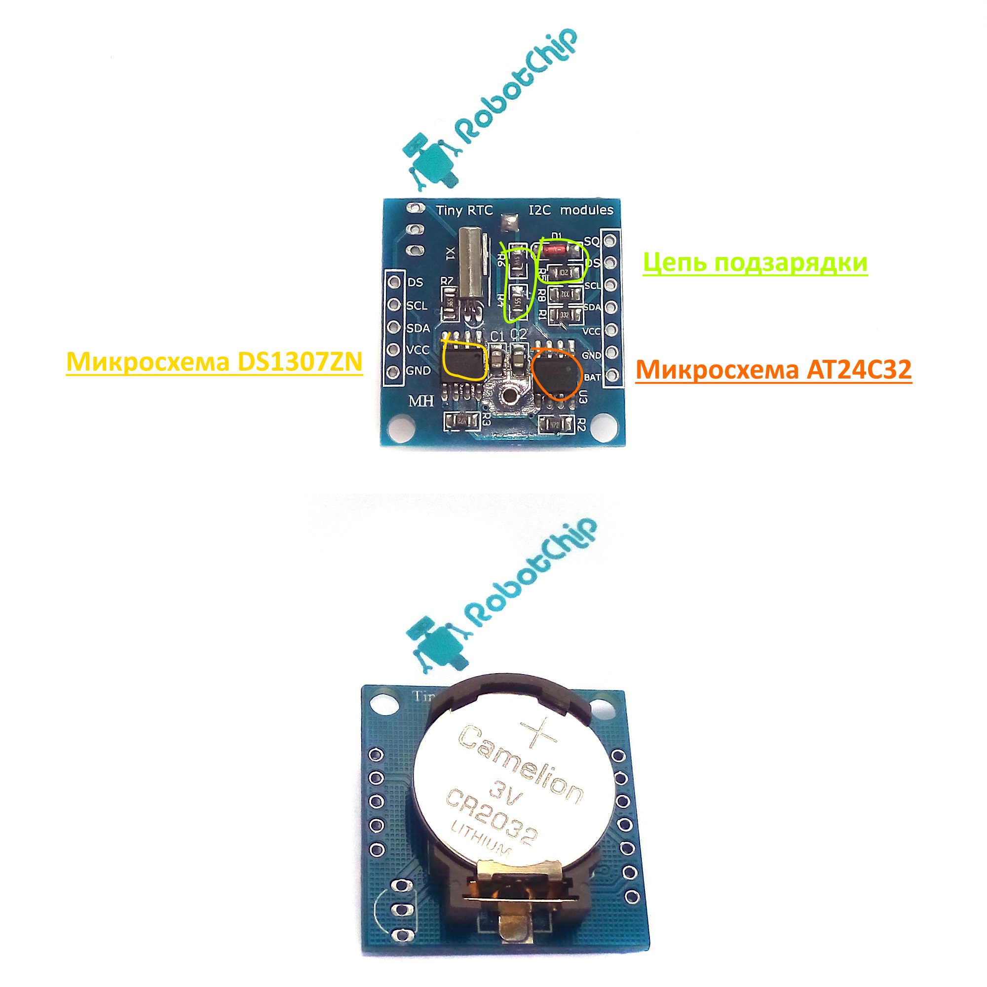
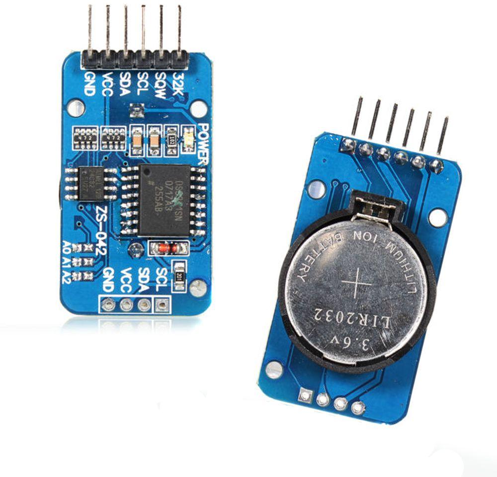
Обмен данными с другими устройствами осуществляется по интерфейсу I2C с выводов SCL и SDA. Конденсаторы С1 и С2 необходимы для снижения помех по линию питания. Чтобы обеспечить надлежащего уровня сигналов SCL и SDA установлены резисторы R2 и R3 (подтянуты к питанию). Для проверки работоспособности модуля, на вывод 7 микросхему DS1307Z, подается сигнал SQ, прямоугольной формы с частотой 1 Гц. Элементы R4, R5, R6, VD1 необходимы для подзарядку литиевой батарейки. Так же, на плате предусмотрено посадочное место (U1), для установки датчика температуры DS18B20 (при необходимости можно впаять его), считывать показания, можно с вывода DS, который подтянут к пиатнию, через резистор R1 сопротивлением 3.3 кОм. Принципиальную схему и назначение контактов можно посмотреть на рисунках ниже.
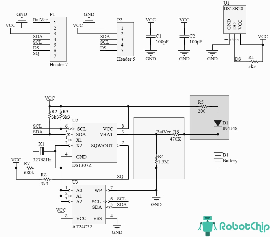
На плате расположено две группы контактов, шагом 2.54 мм, для удобного подключения к макетной плате, буду использовать штырьевые разъемы, их необходимо впаять.
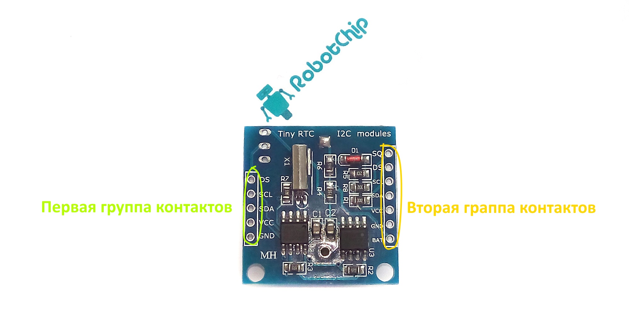
Первая группа контактов:► DS: вывод DS18B20 (1-wire)► SCL: линия тактирования (Serial CLock)► SDA: линия данных (Serial Dфta)► VCC: «+» питание модуля► GND: «-» питание модуля
Вторая группа контактов:► SQ: вход 1 МГц► DS: вывод DS18B20 (1-wire)► SCL: линия тактирования (Serial CLock)► SDA: линия данных (Serial Dфta)► VCC: «+» питание модуля► GND:«-» питание модуля► BAT:
Подзарядка батареи
Как описывал ваше модуль может заряжать батарею, реализовано это, с помощью компонентов R4, R5, R6 и диода D1. Но, данная схема имеет недостаток, через резистор R4 и R6 происходит разряд батареи (как подметил пользователь ALEXEY, совсем не большой). Так как модуль потребляем незначительный ток, можно удалить цепь питания, для этого убираем R4, R5, R6 и VD1, вместо R6 поставим перемычку (после удаления компонентов, можно использовать обычную батарейку CR2032).
Constructor
Description
For AVR architecture only (for backwards compatibility with the DS1307RTC library), the DS3232RTC library instantiates a DS3232RTC object named ; the user should not use the constructor for AVR boards. For other architectures, the user’s code must instantiate a DS3232RTC object.
Parameters
initI2C: An optional parameter to control whether the constructor initializes the I2C bus. The default is true (again for backwards compatibility). (bool)
Example
// For non-AVR boards only. Not needed for AVR boards.
DS3232RTC myRTC(false);     // tell constructor not to initialize the I2C bus.
DS1307 RTC Module Pinout
The DS1307 RTC module has total 7 pins that interface it to the outside world. The connections are as follows:
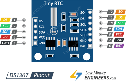
SQW pin outputs one of four square-wave frequencies 1Hz, 4kHz, 8kHz or 32kHz and can be enabled programmatically.
DS pin is supposed output temperature readings if your module has a DS18B20 temperature sensor installed right next to the battery holder(labled as U1).
SCL is the clock input for the I2C interface and is used to synchronize data movement on the serial interface.
SDA is the data input/output for the I2C serial interface.
VCC pin supplies power for the module. It can be anywhere between 3.3V to 5.5V.
GND is a ground pin.
BAT is a backup supply input for any standard 3V lithium cell or other energy source to maintain accurate timekeeping when main power to the device is interrupted.
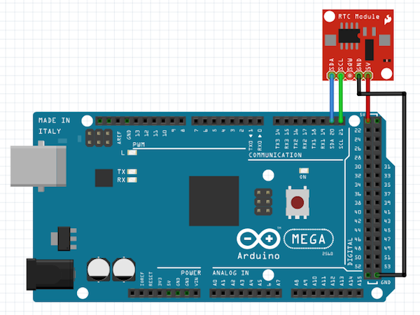
DS3231 Real Time Clock
The DS3231 is a low-cost, highly accurate Real Time Clock which can maintain hours, minutes and seconds, as well as, day, month and year information. Also, it has automatic compensation for leap-years and for months with fewer than 31 days.
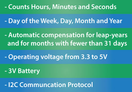
The module can work on either 3.3 or 5 V which makes it suitable for many development platforms or microcontrollers. The battery input is 3V and a typical CR2032 3V battery can power the module and maintain the information for more than a year.
The module uses the I2C Communication Protocol which makes the connection to the Arduino Board very easy.
Here’s the circuit schematics:

So all we need is 4 wires, the VCC and the GND pins for powering the module, and the two I2C communication pins, SDA and SCL.
You can get the components needed for this Arduino Tutorial from the links below:
- DS3231 Real Time Clock…………….. Amazon / Banggood / AliExpress
- Arduino Board …………………………… Amazon / Banggood / AliExpress
- Breadboard and Jump Wires ……… Amazon / Banggood / AliExpress
Disclosure: These are affiliate links. As an Amazon Associate I earn from qualifying purchases.
DS3231 RTC Module Features and Specifications
- Operating Voltage: 2.3 – 5.5 Volts
- Operating Temperature: -45 – 800C
- Maximum Voltage: VCC+0.3 Volts
- Battery Backup Current: 500 mA
- Accuracy at -40 – 800C: ±3.5 ppm
- Accuracy at 0 – 400C: ± 2.0 ppm
- Temperature Accuracy: 30C
- Package-Type: 16, 300-mil SO package
Detailed Features
Some of the detailed features are listed below:
- Can function with low voltages
- A programmable Square-wave output as per requirement
- A battery backup to stay updated even if there is no power
- A dual-directional, 400 kHz of I2C interface for speedy transmission
- 32 bytes of EEPROM for to read/write or to save data
- 2 Time-of-day alarm clocks
- A pushbutton to reset time
- RTC can be used either in 12hrs or 24hrs format
- An aging trim register to set a user-provided value as an offset with reference to the factory value
- Maintains seconds, minutes, hours, days, weeks, months, years information
- Switches automatically from a power source to an in-built battery source
Установка времени
Для установки времени воспользуемся другим примером из этой же библиотеки.
Откроем пример Файл → Образцы → DS1307RTC → SetTime и загрузим его в Arduino.
Отобразить/скрыть пример кода SetTime
#include <Wire.h>
#include <Time.h>
#include <DS1307RTC.h>
const char *monthName = {
«Jan», «Feb», «Mar», «Apr», «May», «Jun»,
«Jul», «Aug», «Sep», «Oct», «Nov», «Dec»
};
tmElements_t tm;
void setup()
{
bool parse=false;
bool config=false;
// получаем дату и время на момент компиляции
if (getDate(__DATE__) && getTime(__TIME__))
{
parse = true;
// и конфигурируем RTC используя эту информацию
if (RTC.write(tm))
{
config = true;
}
}
Serial.begin(9600);
while (!Serial) ; // ожидаем ответа порта
delay(200);
if (parse && config)
{
Serial.print(«DS1307 configured Time=»);
Serial.print(__TIME__);
Serial.print(«, Date=»);
Serial.println(__DATE__);
}
else if (parse)
{
Serial.println(«DS1307 Communication Error :-{«);
Serial.println(«Please check your circuitry»);
}
else
{
Serial.print(«Could not parse info from the compiler, Time=\»»);
Serial.print(__TIME__);
Serial.print(«\», Date=\»»);
Serial.print(__DATE__);
Serial.println(«\»»);
}
}
void loop()
{
}
bool getTime(const char *str)
{
int Hour, Min, Sec;
if (sscanf(str, «%d:%d:%d», &Hour, &Min, &Sec) != 3) return false;
tm.Hour = Hour;
tm.Minute = Min;
tm.Second = Sec;
return true;
}
bool getDate(const char *str)
{
char Month;
int Day, Year;
uint8_t monthIndex;
if (sscanf(str, «%s %d %d», Month, &Day, &Year) != 3) return false;
for (monthIndex = 0; monthIndex < 12; monthIndex++)
{
if (strcmp(Month, monthName) == 0) break;
}
if (monthIndex >= 12) return false;
tm.Day = Day;
tm.Month = monthIndex + 1;
tm.Year = CalendarYrToTm(Year);
return true;
}
|
1 2 3 4 5 6 7 8 9 10 11 12 13 14 15 16 17 18 19 20 21 22 23 24 25 26 27 28 29 30 31 32 33 34 35 36 37 38 39 40 41 42 43 44 45 46 47 48 49 50 51 52 53 54 55 56 57 58 59 60 61 62 63 64 65 66 67 68 69 70 71 72 73 74 75 76 77 78 79 80 81 82 83 84 |
#include <Wire.h> constchar*monthName12={ «Jan»,»Feb»,»Mar»,»Apr»,»May»,»Jun», «Jul»,»Aug»,»Sep»,»Oct»,»Nov»,»Dec» }; tmElements_ttm; voidsetup() { boolparse=false; boolconfig=false; // получаем дату и время на момент компиляции if(getDate(__DATE__)&&getTime(__TIME__)) { parse=true; // и конфигурируем RTC используя эту информацию if(RTC.write(tm)) { config=true; } } Serial.begin(9600); while(!Serial);// ожидаем ответа порта delay(200); if(parse&&config) { Serial.print(«DS1307 configured Time=»); Serial.print(__TIME__); Serial.print(«, Date=»); Serial.println(__DATE__); } elseif(parse) { Serial.println(«DS1307 Communication Error :-{«); Serial.println(«Please check your circuitry»); } else { Serial.print(«Could not parse info from the compiler, Time=\»»); Serial.print(__TIME__); Serial.print(«\», Date=\»»); Serial.print(__DATE__); Serial.println(«\»»); } } voidloop() { boolgetTime(constchar*str) { intHour,Min,Sec; if(sscanf(str,»%d:%d:%d»,&Hour,&Min,&Sec)!=3)returnfalse; tm.Hour=Hour; tm.Minute=Min; tm.Second=Sec; returntrue; } boolgetDate(constchar*str) { charMonth12; intDay,Year; uint8_tmonthIndex; if(sscanf(str,»%s %d %d»,Month,&Day,&Year)!=3)returnfalse; for(monthIndex=;monthIndex<12;monthIndex++) { if(strcmp(Month,monthNamemonthIndex)==)break; } if(monthIndex>=12)returnfalse; tm.Day=Day; tm.Month=monthIndex+1; tm.Year=CalendarYrToTm(Year); returntrue; } |
Открыв монитор порта, видим, что время теперь установлено правильно
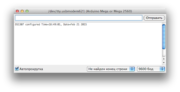
Вновь вернемся к примеру ReadTest, скомпилируем его, загрузим в микроконтроллер и посмотрим на результат.
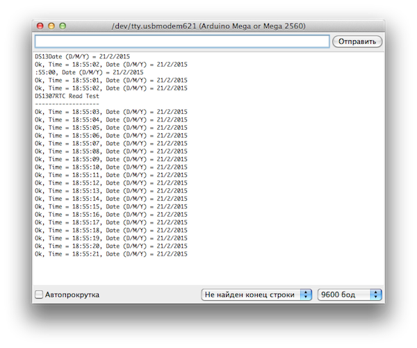
Теперь мы видим, что время актуально и часы тикают.
Battery Backup
The DS1307 incorporates a battery input, and maintains accurate timekeeping when main power to the device is interrupted.
The built-in power-sense circuit continuously monitors the status of VCC to detect power failures and automatically switches to the backup supply. So, you need not worry about power outages, your MCU can still keep track of time.
The bottom side of the board holds a battery holder for 20mm 3V lithium coincells. Any CR2032 battery can fit well.
Assuming a fully charged CR2032 battery with capacity 47mAh is used and chip consumes its minimum 300nA, the battey can keep the RTC running for a minimum of 17.87 years without an external 5V power supply.
47mAh/300nA = 156666.67 hours = 6527.78 days = 17.87 years
Скачать стандартные библиотеки Arduino IDE на русском
Библиотеки для Ардуино делятся на две группы — стандартные и пользовательские. При установке Arduino IDE в папке Program Files\Arduino\libraries имеется набор стандартных библиотек для базовых функций видов, коммуникации платы и для подключения устройств: сервомоторов, шаговых двигателей, LCD-дисплеев и т.д. Стандартные библиотеки скачать можно на официальном сайте www.arduino.cc.
Список стандартных библиотек Arduino:
EEPROM — чтение и запись в энергонезависимую память (скачать eeprom.h)Ethernet — связь с Интернет с помощью Ethernet Shield (скачать ethernet.h)Firmata — для взаимодействия Arduino и ПК (скачать firmata.h)GSM — коммуникация по GSM/GRPS протоколу для GSM Shield (скачать gsm.h)LiquidCrystal — управление LCD дисплеем (скачать liquidcrystal.h)SD — чтение и запись в SD карту (скачать sd.h)Servo — управление серво двигателем (скачать servo.h)SPI — для взаимодействия Arduino и периферийных устройств (скачать spi.h)SoftwareSerial — коммуникация по цифровому порту (скачать softwareserial.h)Stepper — управление шаговым двигателем (скачать stepper.h)TFT — вывод текста и картинок на TFT дисплее (скачать ethernet.h)WiFi — связь с Интернет с помощью WiFi Shield (скачать wifi.h)Wire — коммуникация по протоколу I2C (скачать wire.h)
Functions for setting and reading the time
get(void)
Description
Reads the current date and time from the RTC and returns it as a time_t value. Returns zero if an I2C error occurs (RTC not present, etc.).
None.
Current date and time (time_t)
Example
time_t myTime;
myTime = RTC.get();
set(time_t t)
Description
Sets the RTC date and time to the given time_t value. Clears the oscillator stop flag (OSF) bit in the control/status register. See the function and also the DS323x datasheet for more information on the OSF bit.
t: The date and time to set the RTC to (time_t)
Example
//this example first sets the system time (maintained by the Time library) to
//a hard-coded date and time, and then sets the RTC from the system time.
//the setTime() function is part of the Time library.
setTime(23, 31, 30, 13, 2, 2009);   //set the system time to 23h31m30s on 13Feb2009
RTC.set(now());                     //set the RTC from the system time
read(tmElements_t &tm)
Description
tm: Address of a tmElements_t structure to which the date and time are returned.
I2C status (byte). Returns zero if successful. The date and time read from the RTC are returned to the tm parameter.
Example
tmElements_t tm;
RTC.read(tm);
Serial.print(tm.Hour, DEC);
Serial.print(':');
Serial.print(tm.Minute,DEC);
Serial.print(':');
Serial.println(tm.Second,DEC);
Description
Sets the RTC to the date and time given by a tmElements_t structure. Clears the oscillator stop flag (OSF) bit in the control/status register. See the function and also the DS323x datasheet for more information on the OSF bit.
Example
tmElements_t tm;
tm.Hour = 23;             //set the tm structure to 23h31m30s on 13Feb2009
tm.Minute = 31;
tm.Second = 30;
tm.Day = 13;
tm.Month = 2;
tm.Year = 2009 - 1970;    //tmElements_t.Year is the offset from 1970
RTC.write(tm);            //set the RTC from the tm structure
DS1307 RTC chip
At the heart of the module is a low-cost, quite accurate RTC chip from Maxim – DS1307. It manages all timekeeping functions and features a simple two-wire I2C interface which can be easily interfaced with any microcontroller of your choice.
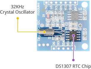
The chip maintains seconds, minutes, hours, day, date, month, and year information. The date at the end of the month is automatically adjusted for months with fewer than 31 days, including corrections for leap year (valid up to 2100). The clock operates in either the 24-hour or 12-hour format with an AM/PM indicator.
The other cool feature of this board comes with SQW pin, which outputs one of four square-wave frequencies 1Hz, 4kHz, 8kHz or 32kHz and can be enabled programmatically.
DS1307 come with an external 32kHz crystal for time-keeping. The problem with these crystals is that external temperature can affect their oscillation frequency. This change in frequency is negligible but it surely adds up.
This may sound like a problem, but it’s not. It actually results with the clock being off by around five or so minutes per month.
Circuit #
- Both the I2C display and the real-time clock board communicate via I2C. To ease the connection, you can create the I2C bus on the breadboard by wiring the and I2C pins from the Arduino board to the contact lines on the breadboard. The display and RTC have different I2C addresses, they do not interfere with each other, so you can connect them to the same I2C bus.
- Connect the and pins from the Arduino board to the corresponding rails on the breadboard.
- Plug the I2C display. Wire its and with the I2C bus on the breadboard. Wire its and pins with the line on the breadboard. Wire pin with the line on the breadboard.
- Plug the I2C RTC breakout board. Wire its and with the I2C bus on the breadboard. Wire its and pins with the corresponding lines on the breadboard.
- Power the RTC board with the battery to keep running even when the external power source is disconnected.
Note
If you are using another model of the I2C display or RTC module, look at their pinout and datasheet to connect them correctly.
Похожие записи:
 Лобзиковый станок из компрессора от холодильника (с масляной ванной)
 Как правильно установить чугунную ванну: варианты крепления, советы по заносу и выравниванию
 Что можно сделать из старой стиральной машины
 Сатиновые натяжные потолки: особенности и технология монтажа
 Как выбрать хороший газовый счетчик для квартиры и не переплатить
 Digispark attiny85