Содержание
Модуль ISD1820
Модуль диктофона ISD1820 основан на микросхеме ISD1820, которая представляет собой однокристальную ИС диктофона для записи и воспроизведения отдельных сообщений. Главная особенность модуля диктофона ISD1820 заключается в том, что он может хранить сообщения в своей энергонезависимой памяти и может быть сконфигурирован для хранения сообщений длиной от 8 секунд до 20 секунд.
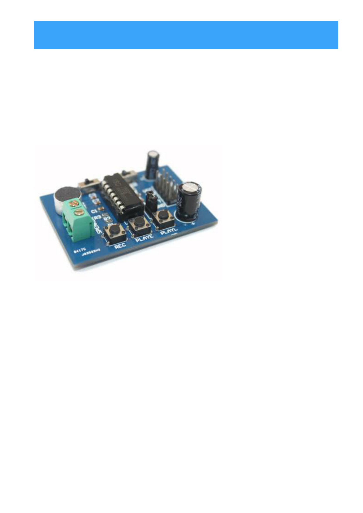
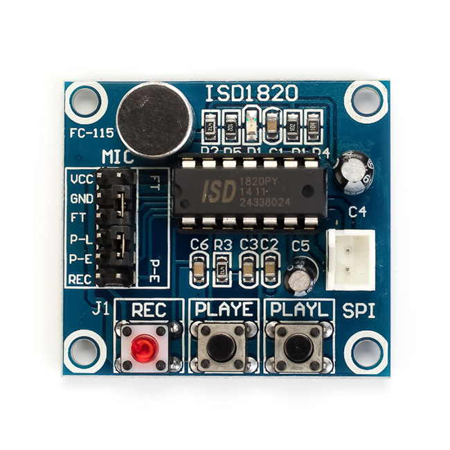
Модуль диктофона ISD1820, используемый в этом проекте, показан ниже. Как видите, на плате много компонентов, которые помогают микросхеме ISD1820 в записи и воспроизведении.
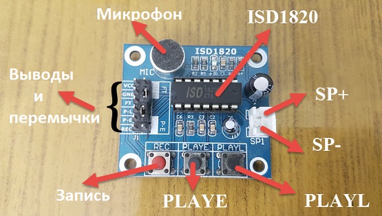
Еще одной главной особенностью этого модуля является то, что он имеет встроенный аудиоусилитель, который может управлять динамиком 0,5 Вт 8 Ом напрямую, без необходимости использования какой-либо внешней схемы усилителя. Но если вы хотите подключить более мощные динамики, вы можете подключить выход этого модуля к ИС внешнего усилителя, например, LM386.
Как работать с модулем ISD1820? Подключите небольшой 8-Омный динамик к выходу модуля, то есть через контакты SP+ и SP-. Нажмите кнопку записи (REC) на модуле, и модуль начнет запись. Продолжайте удерживать нажатой кнопку до тех пор, пока не запишите полное сообщение (например, около 10 секунд). Для воспроизведения вы можете использовать PLAYE или PLAYL. Нажмите кнопку PLAYE один раз, и все сообщение будет воспроизведено. Вам нужно нажать и удерживать кнопку PLAYL, и сообщение начнет воспроизводиться, и, если вы хотите остановить воспроизведение в любой момент, отпустите кнопку. Если вы активируете перемычку PE, воспроизведение происходит в режиме бесконечного цикла.
Datasheet Download — ETC
| Номер произв | ISD1820 | ||
| Описание | Voice Record Module | ||
| Производители | ETC | ||
| логотип | |||
|
1Page
ISD1820 Voice Record Module is base on ISD1820, which a multiple-message record/playback device. It can offers true single-chip voice recording, no-volatile storage, and playback capability for 8 to 20 seconds. The sample is 3.2k and the total 20s for the Recorder. Push-button interface, playback can be edge or level activated Automatic power-dwon mode On-chip 8Ω speaker driver Signal 3V Power Supply Can be controlled both manually or by MCU Sample rate and duration changable by replacing a single resistor Record up to 20 seconds of audio Dimensions: 37 x 54 mm If you want change record duration, an external resistor is necessary to select the record duration and sampling frequency, which can range from 8 – 20 seconds (4-12kHz sampling frequency). The Voice Record Module of our provide default connect 100k resistor through P2 by short cap. So the default record
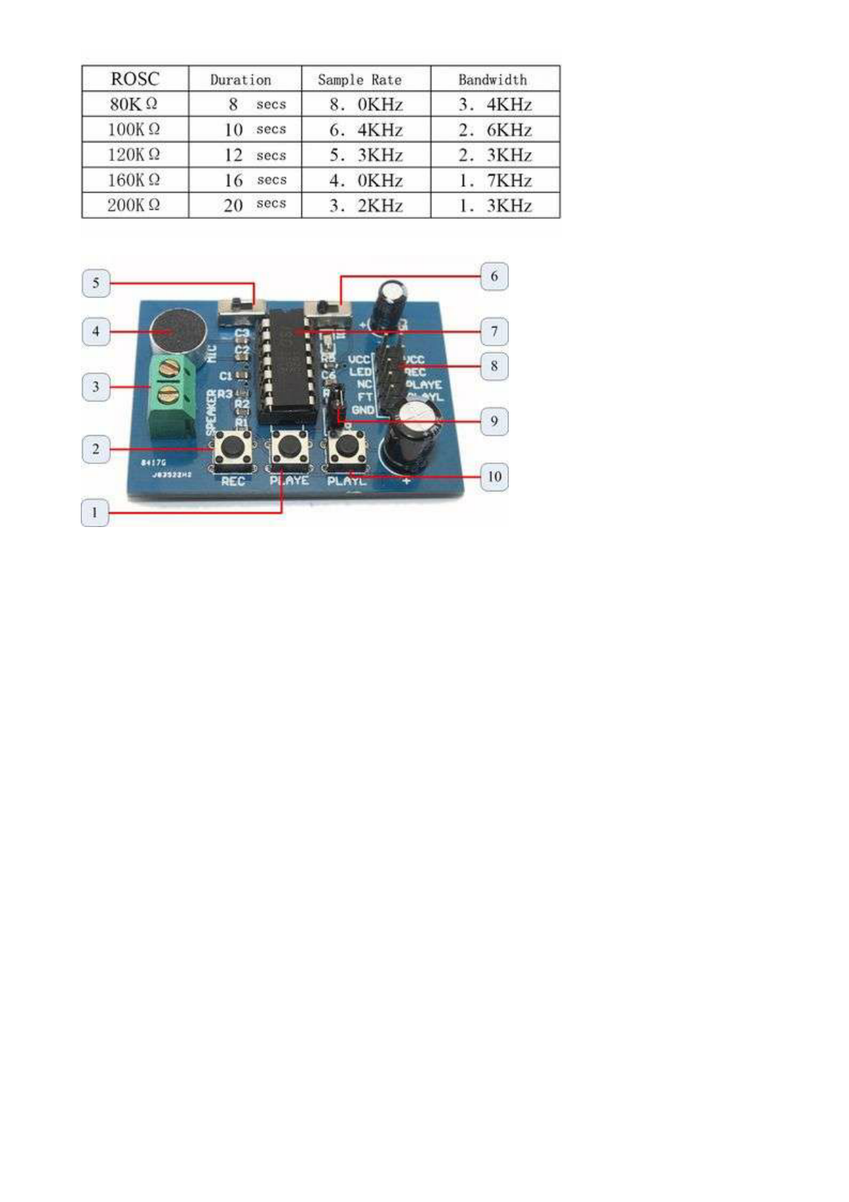
1. PLAYE – Playback, Edge-activated:When a HIGH-going transition is detected on continues until an End-of-Message (EOM) marker is encountered or the end of the memory space is reached. 2. REC – The REC input is an active-HIGH record signal.The device records whenever REC is HIGH. This pin must remain HIGH for the duration of the recording. REC takes precedence over either 3. Speaker Outputs – The SP+ and SP- pins provide direct drive for loudspeakers with impedances as low as 8Ω. 4. MIC – Microphone Input, the microphone input transfers its signals to the on-chip preamplifier. 5. REPLAY – loop play the record. 6. FT – Feed Through: This mode allows use of the speaker drivers for external signals. 7. ISD1820 – IC chip 8. Lead Out IO – VCC LED NC FT GND / VCC REC PLAYE PLAYL GND 9. P2 – default short connection ROSC to 100kΩ resistance, that’s means record duration is 10s 10. PLAYL – Playback, Level-activated, when this input pin level transits for LOW to HIGH, a playback cycle is initiated. 3. Select Playback mode: PLAYE, just need push one time, and will playback all of the record or power down ; PLAYL, you need always push this button until you want to stop playback record or Free Datasheet http://www.nDatasheet.com
end ; REPEAT, switch 5 to right side, and the record will playback time a time until switch to light or power down Then we control PIR Sensor and Voice record module by Freaduino ATMage328. Of course you can also use PIR and record function. Use your imagination. |
|||
| Всего страниц | 5 Pages | ||
| Скачать PDF |

ISD1820 Arduino Voice Record/Playback Tutorial
By Sharath Arduino
Like:
The Voice Record Module is based on the ISD1820 chip, a multiple‐message record/playback device.
It can offer true single‐chip voice recording, non-volatile storage, and playback capability for 8 to 20 seconds. The sample rate is between 8.0 KHz to 3.2 KHz for the duration of 8 to 20 Seconds for the Recorder.
This module use is very easy to use, which you could direct control by the push button on board or by Microcontroller such as Arduino, STM32, ChipKit etc.
Specifications
- Push-button interface, playback can be edge or level activated
- Automatic power-down mode
- On-chip 8Ω speaker driver
- Signal 3V Power Supply
- Can be controlled both manually or by MCU
- Sample rate and duration changeable by replacing a single resistor
- Record up to 20 seconds of audio
- Dimensions: 37 x 54 mm
If you want change record duration, an external resistor is necessary to select the record duration and sampling frequency, which can range from 8 – 20 seconds (4‐12kHz sampling frequency). The Voice Record Module of our provides default connect 100k resistor by a short cap. So the default record duration is 10s.
| ROSC | Duration | Sample Rate | Bandwidth |
| 80 KΩ | 8 Sec | 8.0 KHz | 3.4 KHz |
| 100 KΩ | 10 Sec | 6.4 KHz | 2.6 KHz |
| 120 KΩ | 12 Sec | 5.3 KHz | 2.3 KHz |
| 160 KΩ | 16 Sec | 4.0 KHz | 1.7 KHz |
| 200 KΩ | 20 Sec | 3.2 KHz | 1.3 KHz |
If you want to extend it to Speakers (High power), you can use LM386, D2283, D2322, TA7368, MC34119 etc amplifier IC.
Pinout
- VCC– 3.3V power supply
- GND– Power ground
- REC – The REC input is an active‐HIGH record signal. The module starts recording whenever REC is HIGH. This pin must remain HIGH for the duration of the recording.
- REC takes precedence over either playback (PLAYL or PLAYE) signal.
- PLAYE – Playback, Edge‐activated: When a HIGH‐going transition is detected on continues until an End‐of-Message (EOM) marker is encountered or the end of the memory space is reached.
- PLAYL – Playback, Level‐activated, when this input pin level transits for LOW to HIGH, a playback cycle is initiated.
- Speaker Outputs – The SP+ and SP‐ pins provide a direct drive for loudspeakers with impedances as low as 8Ω.
- MIC – Microphone Input, the microphone input transfers its signals to the on‐chip preamplifier.
- FT – Feed Through: This mode enable the Microphone to drive the speaker directly.
- P‐E – Play the records endlessly.
You can control the Voice Recorder Module ISD1820 directly with onboard Buttons.
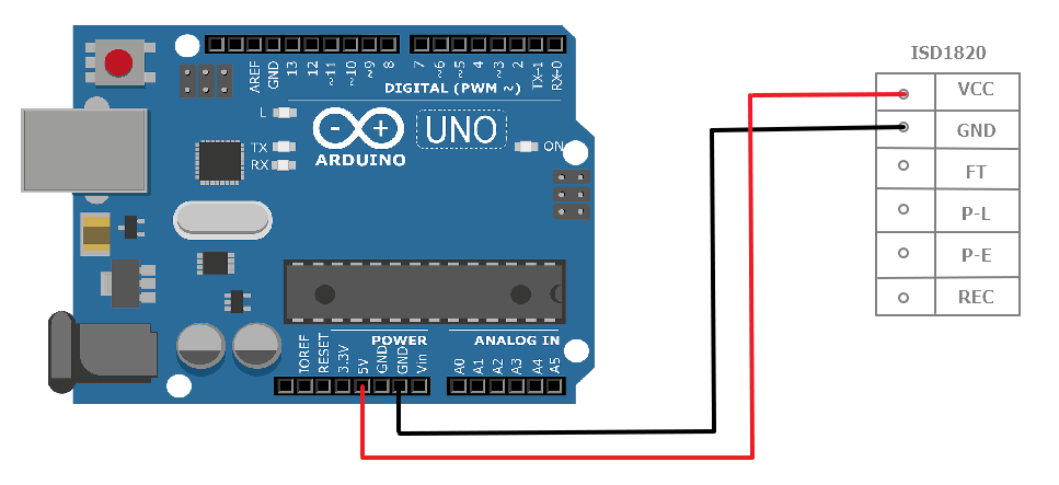
- Connect VCC from ISD1820 to any 3V power supply. In our case, we have connected to 3.3V on Arduino
- Connect GND to GND on Arduino.
Start using the Module!!
- Push REC button then the RECLED will light and keep push until record end.
- Release the REC button
- Select Playback mode:
- PLAYE, just need push one time, and will playback all of the records and until the pre-record sound end.
- PLAYL, you need always push this button until you want to stop playback record or end.
- P-E mode, when short P‐E jumper the record will playback repeatedly until jumper off or power down.
- FT mode, when short FT jumper, that means all of you speak to MIC will direct playback to Speaker.
Leave a Message to your loved ones!!
In this tutorial, we will use IR Sensor, ISD1820 Voice Recorder and Arduino to record and leave a message.
- When you wave across IR sensor it starts recording for 10 Seconds.
- When PLAYE button on the Voice Recorder is pressed it playbacks the recorded voice.
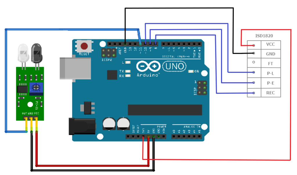
Circuit Connection:
| IR Sensor | Arduino |
| VCC | 5 V |
| GND | GND |
| OUT | 11 |
| ISD1820 Voice Recorder | Arduino |
| VCC | 3.3 V |
| GND | GND |
| REC | 8 |
| P-E | 9 |
| P-L | 10 |
Circuit Diagram:
Code:
#define IR  11

#define REC 8

#define PLAYE 9

#define PLAYL 10


void setup(){

 pinMode(IR, INPUT);

 pinMode(REC, OUTPUT);

 Serial.begin(9600);

}


void loop(){

 int i = digitalRead(IR);

 if(i == 0)

 {

   Serial.println("Someone's here!!");

   digitalWrite(REC, 1);

   delay(10000);

   digitalWrite(REC, 0);

    delay(1000);

    digitalWrite(PLAYE, 1);

   delay(10000);

   digitalWrite(PLAYE, 0);

 }

}
OUR EVALUATION RESULTS:
The beauty of this module is that it is simple to use as it doesn’t have a lot of options to complicate things. We embedded one in a Zombie operation game for a sound effect when the tweezers touched the side and it is perfect for Halloween effects and similar applications.
The sound quality is fair and good enough for most applications that would make use of this device.
To test the device, just apply power and ground to the header pins and hookup a speaker to the screw terminals. Pressing PLAYE will play anything that may have been pre-recorded on the device during testing. To make your own recording, press and hold the REC button and speak into the mic. Pressing PLAYE should replay the audio that you just recorded. If it doesn’t seem to be working, verify that the Audio Feedthru switch is in the OFF position.
The main complaint about this module is that the audio playback volume is on the weak side. To improve that, we make a modification to the modules we sell
A 47K ohm resistor is added from the AGC Input to the LED Output pin. This ensures that the AGC circuit keeps a higher level during recording and hence the playback volume is also increased.
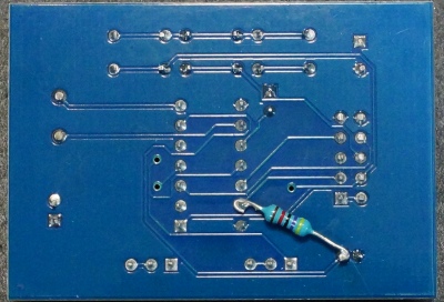
The resistor is added to the back of the board.
Код программы взаимодействия Arduino и ISD1820
Выполните подключения согласно электрической схеме и подайте питание на цепь. Когда перед ИК-датчиком нет объекта, его выход будет в низком логическом состянии, и Arduino ничего не будет делать. Когда перед ИК-датчиком появится какой-либо объект, его выходной сигнал переходит в высокий логический уровень, и Arduino начинает запись сообщения, переводя вывод REC в высокое логическое состояние и поддерживая его в течение примерно 5 секунд. В течение этого времени светодиод, подключенный к контакту 13, будет светиться, чтобы указать, что модуль записывает сообщение. После записи, сообщение воспроизводится посредством перевода вывода PLAYE в высокое логическое состояние и его поддержания в течение примерно 6 секунд.
digitrode.ru
Эхо репитер на ISD1820 + digispark attiny85

Как-то захотелось получить в арсенал такое устройство и начал бороздить сеть на предмет искомого. Первые же запросы гугломашины указывали на тытруб. Перешёл посмотреть ролик на некий канал «HAM Radio Channel». Признаться честно, представление информации в видеороликах не очень информативное, так как в большей части это кино граждан о самих себе, текст и графика же позволяют сократить поток ненужной информации и передать полезную информацию в сжатом объёме и по делу. И тут была допущена ошибка с моей стороны. Так как схемка была не великой, решено было собрать на коленке всё это дело и стартануть. Уже после того, как стало понятно, что предлагаемое устройство в ролике не работоспособно — начался разбор полётов.
Не рабочая схема эхо-репитера
Схема, которую предложил автор ролика:
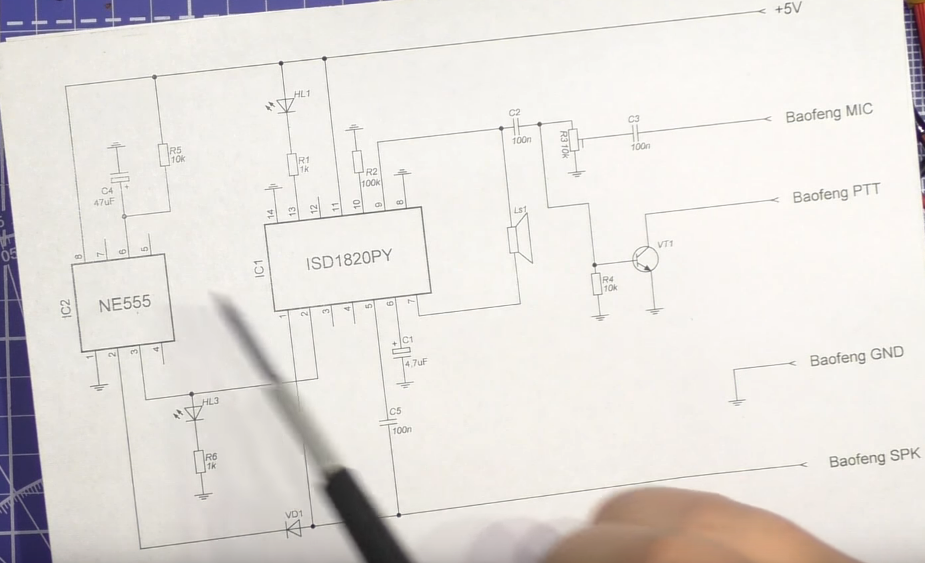
В целом всё выглядит работоспособным, но данная схема не будет работать на передачу так как VT1 просто не откроется сигналом выходящем со спикера, а значит, вероятно, что в ролике на станции включен VOX. И передача активируется не по сигналу PTT. Ну и само устройство работает крайне не стабильно.
Рабочая схема Эхо-репитера
Характеристики:
— Питание 3,3 — 5V
— Потребляемый ток в режиме ожидания: 17mA
— Потребляемый ток в режиме работы: 26mA
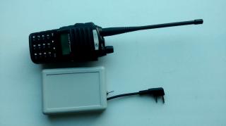
— Размеры устройства в корпусе: 100х75х27
Возможности эхо репитера:- При приёме сигнала, производится запись в течении 10 сек. и через 0.5 сек отправляется в эфир.
— Так же имеет возможно в заданном интервале посылать в эфир позывной.
Узлы эхо репитера:
Модуль записи голоса на базе ISD1820. Стоимость — 84р.
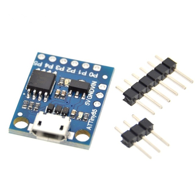
2. Digispark Attiny85. Стоимость — 100р.
3. Модуль зарядки АКБ TP4056. Стоимость — 57р.
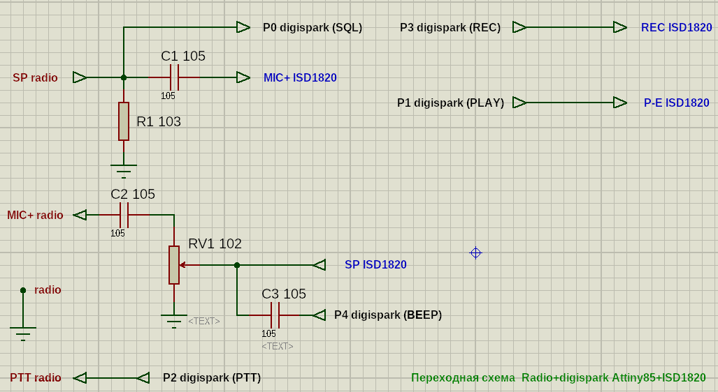
Схема переходной платы для совмещения ISD1820 и Attiny85
Что нужно сделать, чтобы получить из всего этого готовый эхо репитер:
Собрать по выше представленной схеме узлы между собой, залить код в attiny85 в виде digispark, подключить всё это к питанию
Питание у ISD1820 и Digispark общее и на нём заострять внимание нет смысла. В данном репитере реализовывалось через Li-on аккумулятор, зарядником к которому выступает TP4056
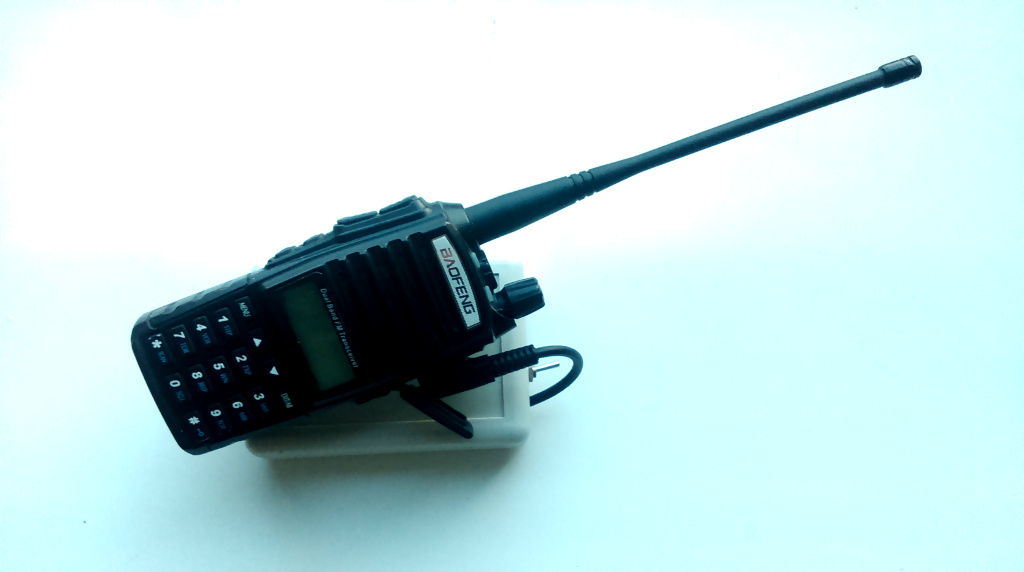
Так выглядит всё в сборе и в корпусе.
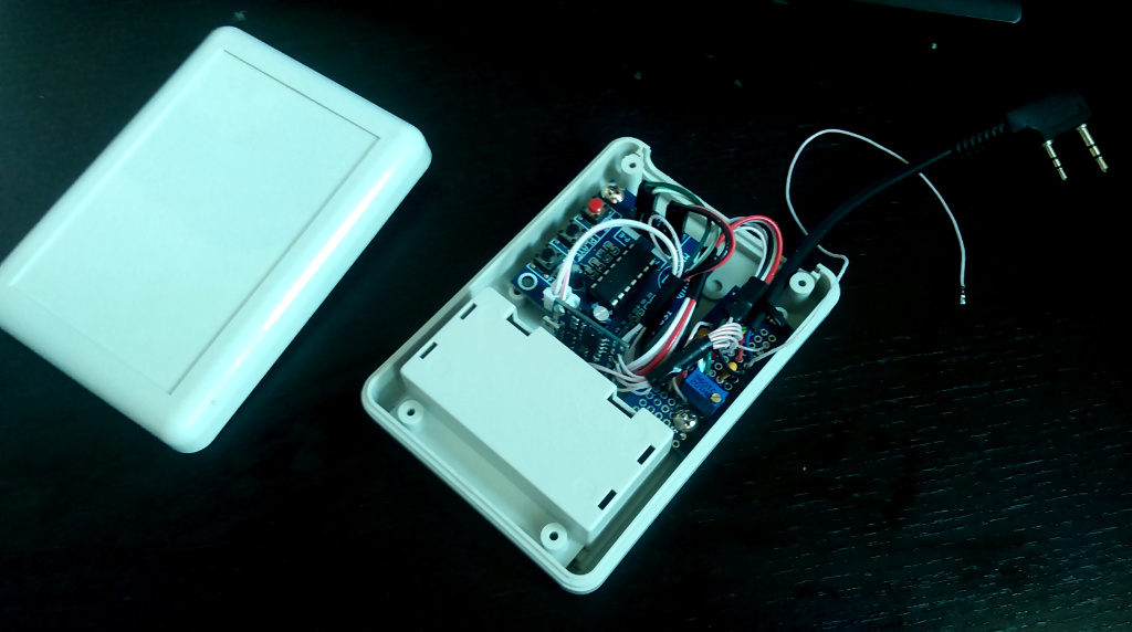

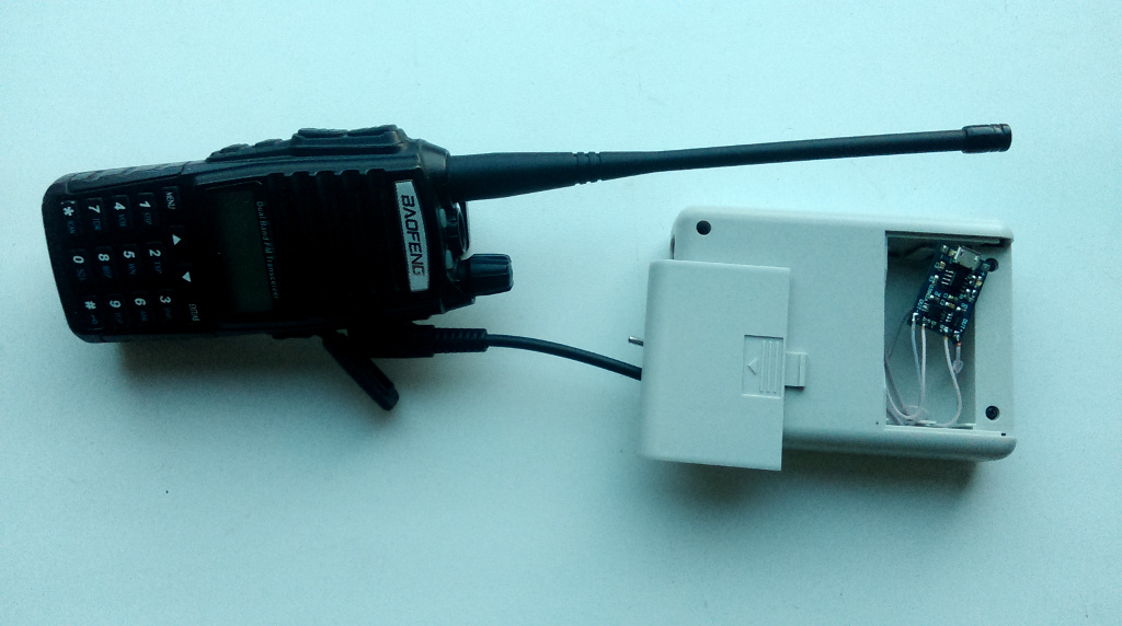
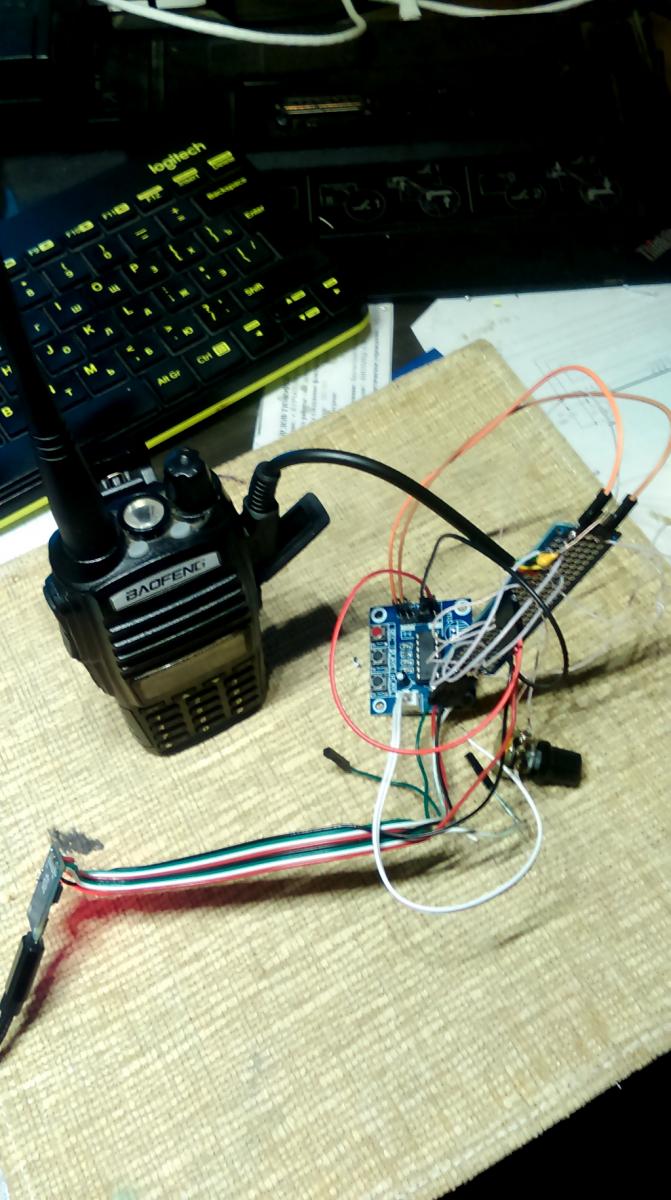
Таким образом всё выглядело на моменте тестовой сборки.
Подключение Arduino к ISD1820
Как было сказано ранее, модуль диктофона ISD1820 может работать независимо без какого-либо микроконтроллера. Но управление функцией записи и воспроизведения с помощью микроконтроллера, такого как, например, Arduino, дает вам возможность расширить функциональные возможности модуля до уровня сложных приложений.
Представьте себе ситуацию, когда вы разрабатываете систему безопасности, которая должна автоматически записывать голос при обнаружении движения. Это будет возможно, только если вы подключите модуль диктофона ISD1820 к Arduino (или к любому микроконтроллеру).
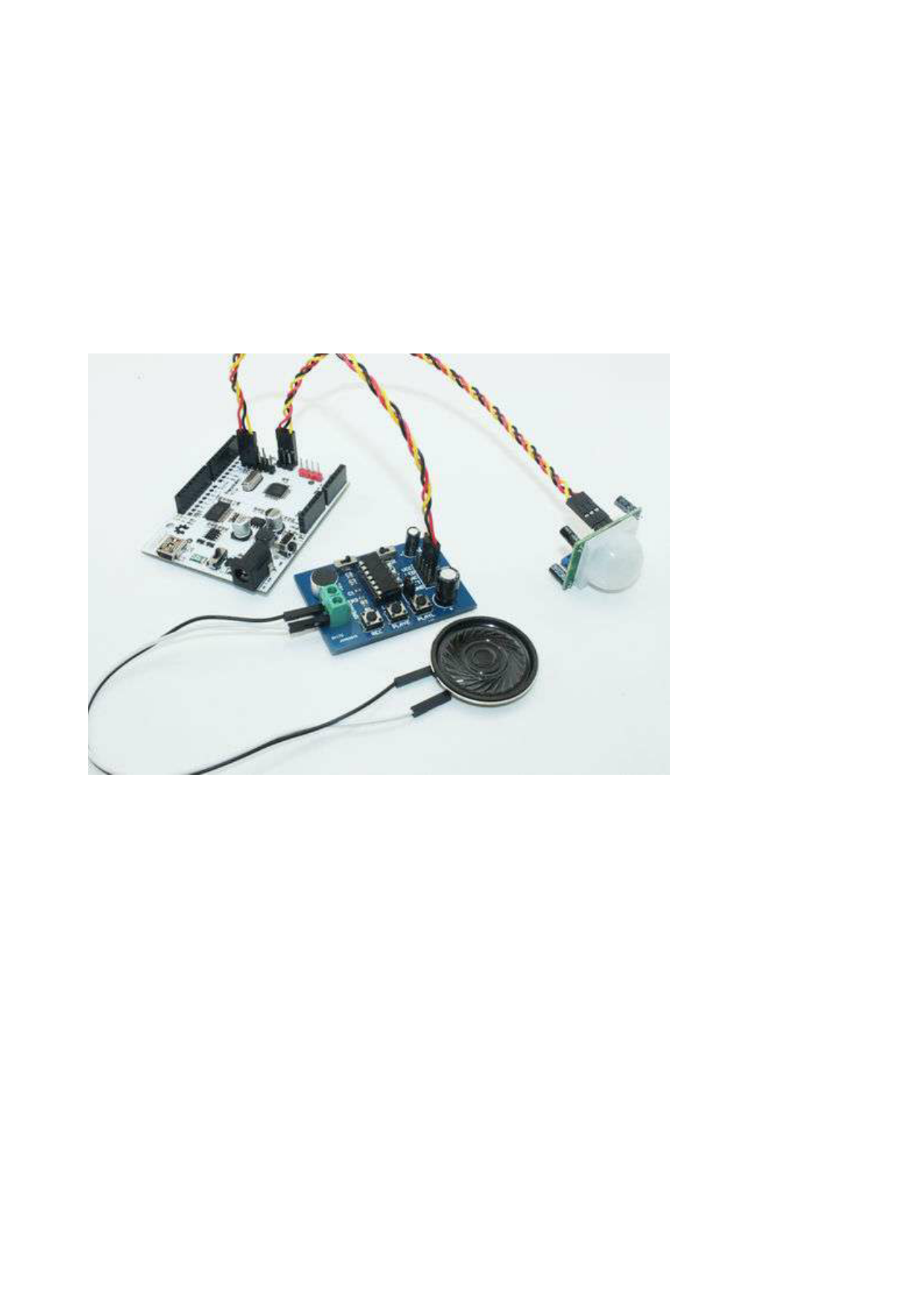
Схема подключения Arduino к ISD1820, а также к ИК-датчику и динамику для реализации такой простой сигнализации с записью голоса, показана ниже.
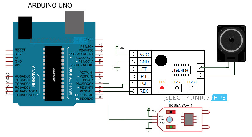
Контакты SP+ и SP- модуля ISD1820 подключены к клеммам динамика. VCC и GND модуля подключены к + 5V и GND. Контакты REC и PLAYE подключены к цифровым контактам 2 и 3 платы Arduino. Здесь используется инфракрасный датчик отражающего типа, а цифровой выход датчика подключен к выводу 4 платы Arduino.
Общее описание
ISD1700 — серия ИС ChipCorder, представляющих собой полностью интегрированное, однокристальное решение для записи/воспроизведения нескольких голосовых сообщений и предназначенных для использования в разнообразных электронных системах. Длительность сообщения задается пользователем в пределах 26…120 секунд (зависит от типа ИС). Возможность задания внешним резистором частоты преобразования в диапазоне 4…12 кГц еще больше увеличивает гибкость по выбору длительности сообщений. ИС способны работать при напряжении питания от 2.4 до 5.5 В, что делает возможным их использование в применениях, как с батарейным питанием, так и с питанием от сети переменного тока.
В ИС серии ISD1700 учтена возможность автономной и совместной работы с микроконтроллером через интерфейс SPI. В ИС входит оригинальная система управления сообщениями, которая позволяет им автоматически управлять адресами нескольких сообщений. Данная уникальная особенность позволяет, при управлении обычными кнопками, реализовать интеллектуальные функции управления сообщениями. В ИС также входят тактовый генератор (управляется внешним резистором), микрофонный предусилитель с АРУ, вспомогательный аналоговый вход, фильтры, энергонезависимая память для хранения аналоговых выборок, схема управления громкостью, усилитель мощности класса D, а также токовый/вольтажный выход.
ИС ISD1700 поддерживают опциональную возможность «vAlert», которую можно использовать для голосовой сигнализации получения нового сообщения. Помимо функции vAlert, о приходе нового сообщения также сигнализирует мигание внешнего светодиода. И кроме того, для подтверждения таких операций, как «Старт записи», «Останов записи», «Стирание», «Вперед», «Общее стирание» и др., предусмотрено четыре звуковых сигнала.
Записи сберегаются во встроенной флэш-памяти, т.о. для их хранения питание не требуется. Появление данного однокристального решения стало возможным, благодаря запатентованной Winbond технологии многоуровневого хранения. Аудиоданные хранятся в твердотельной памяти в их естественном виде (без цифрового сжатия), чем достигается высокое качество воспроизведения голоса и музыки.
Голосовые сигналы могут поступать во флэш-память по двух независимым трактам: через дифференциальные входы микрофонного усилителя и через несимметричный аналоговый вход. Для вывода звуковой информации у ISD1700 предусмотрены усилитель мощности класса D (ШИМ) и параллельно работающий с ним отдельный аналоговый выход. Усилитель мощности может напрямую управлять 8-омным динамиком, а дополнительный аналоговый выход может быть сконфигурирован, как токовый или вольтажный, и предназначен для работы с внешним усилителем.
Когда ИС ISD1700 работают в автономном режиме, они автоматически переходят в дежурный режим работы по завершении каждого рабочего цикла.
В режиме SPI внешний микроконтроллер через последовательный интерфейс получает все функции управления, в т.ч. доступ к любой области внутренней памяти по заданным начальному и конечному адресам. В режиме SPI также имеется возможность доступа к регистру конфигурации аналоговых каскадов (APC).
Данный регистр позволяет гибко настроить аудиокаскады, входы, выходы и микширование. При необходимости изменить настройку по умолчанию регистра APC, нужно сохранить требуемое состояние APC в энергонезависимый регистр NVCFG, содержимое которого перезаписывается в APC во время инициализации.
Т.о. образом ИС ISD1700 обладают всеми возможностями, позволяющие быстро и гибко реализовать голосовые функции в высококачественной продукции.
Отличительные особенности:
KEY FEATURES OF ISD1820 VOICE RECORD AND PLAYBACK MODULE:
- Record and playback up to 10 seconds of audio.
- Pushbutton and MCU controllable
- Edge or level activated playback
- Built-in microphone
- On-chip 8 ohm speaker driver
- Duration and sample rate can be modified up to 20 seconds with resistor change
- Auto power down mode
- 2.6 -5V operation
With the built-in microphone, you can record one message that is up to 10 seconds long. This can be extended up to 20 seconds with a resistor change. The message can be rerecorded up to 100,000 times and is non-volatile.
A small built-in audio amplifier can drive an 8 ohm speaker.
The main features of the module are shown below. Functions such as Record, PlayE and PlayL can be activated by pushing a button or input a logic HIGH on the header pin with the same name.
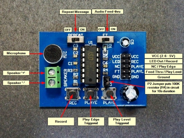
| REC | RECORD – Pin is active HIGH to start recording and must remain high while the recording is in process. The red LED will light while recording. Once the pin goes LOW or it runs out of memory, an End-Of-Message (EOM) marker is automatically recorded.
Pressing and holding down the pushbutton will also record a message. Release the button to stop the recording. |
| PLAYE | PLAY Edge – Pin is edge activated when it transitions to HIGH. The recording will play until the EOM is reached. The pin can be set LOW while message plays and it will not terminate the message. When EOM is reached the red LED will flash.
Pressing the pushbutton will play the entire recorded message. |
| PLAYL | PLAY Level – Pin is active HIGH. When pin goes HIGH, the message will play until the pin is set back to LOW or the EOM is reached.
Pressing the pushbutton will play the recorded message until the button is released or the EOM is reached. |
| REPEAT | REPEAT Switch – if moved to the right will play the recorded message continuously. |
| FT | FT Switch – if moved to the right will enable a Feed Thru mode of operation. In this mode of operation, any audio picked up by the mic will be sent directly out to the speaker |
| LED | LED Output – Normally HIGH, goes LOW when LED is lit |
| VCC | VCC can range from 2.6 to 5.5V. Only one VCC pin needs to be connected |
| GND | Ground should be common with the uC. Only one GND pin needs to be connected |
| NC | No Connect |
The ISD1820 chip has a Resistor Controlled Oscillator input (ROSC) input. A resistor placed between the ROSC pin and ground sets the oscillator frequency and therefore sample rate and thus the maximum duration of the audio. As per the table below, a tradeoff can be made between using a shorter duration recording, but with a higher sample rate and bandwidth or the duration can be extended up to 20 seconds with a lower sample rate and bandwidth.
The module ships with a 100K resistor in location R4 that is connected to the ROSC pin on the ISD1820P chip. It is put into the circuit with the jumper at location P2. 100K is what sets the 10 second duration for the recording. R4 can be replaced, or the jumper can be removed and a different value can be jumpered from the header pin next to R4 to ground to change the recording characteristics per the table below.
| ROSC | Duration | Sample Rate | Bandwidth |
| 80K Ohm | 8 Secs | 8.0kHz | 3.4kHz |
| 100K Ohm | 10 Secs | 6.4kHz | 2.6kHz |
| 120K Ohm | 12 Secs | 5.3kHz | 2.3kHz |
| 160K Ohm | 16 Secs | 4.0kHz | 1.7kHz |
| 200K Ohm | 20 Secs | 3.2kHz | 1.3kHz |
It is also possible to record at one rate and play back at another. That will serve to speed up or slow down the playback which might be useful for creating sound effects. A pot can be wired in for this purpose.
The power output is sufficient to drive a small speaker or the output can be used to drive the input of an audio amplifier if a louder sound is desired.